
Hydraulic micro-displacement driver and micro-displacement device

A micro-displacement driver and micro-displacement technology, which is applied in the field of precision machinery, can solve the problems of small maximum displacement of the moving stroke and difficulty of the piezoelectric crystal driver to overcome the small driving stroke, durable anti-interference ability, and large driving stroke Effect

Inactive Publication Date: 2014-02-05
江苏尚飞光电科技股份有限公司 +2
View PDF7 Cites 1 Cited by
  • Summary
  • Abstract
  • Description
  • Claims
  • Application Information

AI Technical Summary

Problems solved by technology

The obvious shortcoming of all kinds of existing micro-linear displacement drivers is that the moving stroke (that is, the maximum displacement) is small. For example, in the occasions that require micro-nanometer precision and millimeter-level strokes, piezoelectric crystal drivers are not competent.

Method used


Image

  • Hydraulic micro-displacement driver and micro-displacement device
  • Hydraulic micro-displacement driver and micro-displacement device
  • Hydraulic micro-displacement driver and micro-displacement device

Examples


Embodiment Construction

[0027] Embodiments of the present invention are described below through specific examples, and those skilled in the art can easily understand other advantages and effects of the present invention from the content disclosed in this specification. The present invention can also be implemented or applied through other different specific implementation modes, and various modifications or changes can be made to the details in this specification based on different viewpoints and applications without departing from the spirit of the present invention.

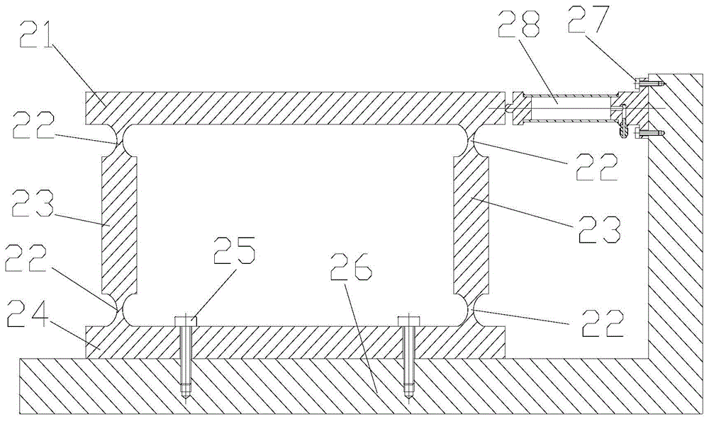
[0028] see Figure 1 to Figure 3 . It should be noted that the diagrams provided in this embodiment are only schematically illustrating the basic idea of ​​the present invention, and only the components related to the present invention are shown in the diagrams rather than the number, shape and shape of the components in actual implementation. Dimensional drawing, the type, quantity and proportion of each component can be changed arb...


PUM


Abstract

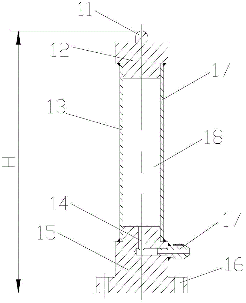
The invention provides a hydraulic micro-displacement driver and a micro-displacement device. The hydraulic micro-displacement driver at least comprises a cylinder barrel (13) with an inner cavity (18), an upper end cover (12) and a lower end cover (15) used for sealing the two ends of the cylinder barrel (13), a spherical boss (11) positioned on the upper surface of the upper end cover, an oil inlet channel (14) arranged in the lower end cover (15) and communicated with the inner cavity, and an oil inlet nozzle (17) communicated with the oil inlet channel (14), wherein the central line of the spherical boss coincides with the central line of the cylinder barrel. According to the hydraulic micro-displacement driver provided by the invention, the sealed cylindrical and tubular cylinder barrel is filled with liquid with certain pressure to correspondingly axially elongate, so as to realize micro-displacement driving; the hydraulic micro-displacement driver has the characteristics of larger driving stroke, high stability in driving, high anti-interference ability, durability and the like, and overcomes the defects about small driving stroke of piezoelectric crystal and poorer stability.

Description

technical field [0001] The invention relates to the field of precision machinery, in particular to a hydraulic micro-displacement driver and a micro-displacement device. Background technique [0002] Linear micro-displacement actuators are mainly used to drive guide rails to produce high-precision linear displacements, and have important applications in the fields of micro-nano processing equipment, micro-nano detection instruments, and other optical precision machinery. At present, the vast majority of micro-displacement drivers work based on the inverse piezoelectric effect of crystals, such as piezoelectric ceramic drivers. The obvious shortcoming of all kinds of existing micro-linear displacement drivers is that the moving stroke (that is, the maximum displacement) is small. For example, in the occasions that require micro-nanometer precision and millimeter-level strokes, piezoelectric crystal drivers are not competent. [0003] figure 1 is the schematic diagram of the...

Claims


Application Information

Patent Timeline
IPC IPC(8): B81B3/00
Inventor 黄海阳武爱民甘甫烷盛振李伟
Owner 江苏尚飞光电科技股份有限公司
Learn More