A special-shaped pipe wall screw conveyor

A screw conveyor and special-shaped pipe technology, applied in the field of conveyors, can solve the problems of continuous non-pulsation feeding, large gap between pipe wall and spiral blade, affecting unloading and air lock, etc., to achieve continuous non-pulsation feeding , reduce the filling factor, and facilitate installation and maintenance

Active Publication Date: 2016-04-13
CHINA COAL RES INST CCRI ENERGY SAVING TECH CO LTD
View PDF6 Cites 0 Cited by
  • Summary
  • Abstract
  • Description
  • Claims
  • Application Information

AI Technical Summary

Problems solved by technology

However, the screw conveyors with the above two structural forms have the following two disadvantages: 1) they cannot continuously feed materials without pulsation, and in practical applications, they can realize the feeding of one lead per revolution, that is, intermittent feeding; 2) ) After long-term use, the friction and wear between the pipe wall and the spiral blade and the powder body will cause the gap between the pipe wall and the spiral blade to become larger, thus affecting the discharge and air lock

Method used


Image

  • A special-shaped pipe wall screw conveyor
  • A special-shaped pipe wall screw conveyor

Examples


Embodiment Construction

[0012] The present invention will be described in detail below in conjunction with the accompanying drawings and embodiments.

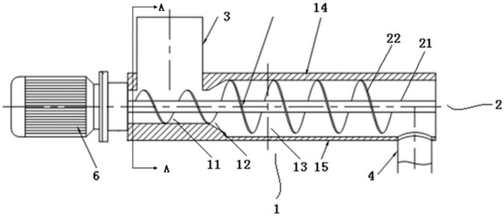
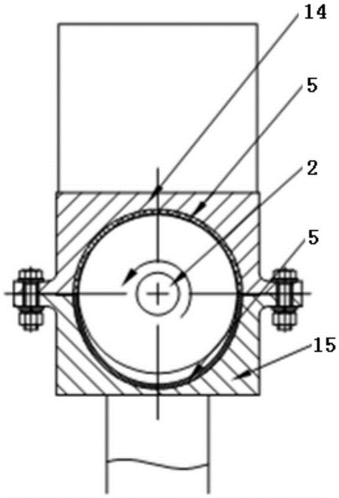
[0013] Such as figure 1 , figure 2 As shown, the present invention includes a feeding pipe 1 , a screw propeller 2 , a material inlet 3 , a material outlet 4 and a motor 6 . The feeding pipe 1 is arranged horizontally, the upper part of one end is connected with the material inlet 3, and the lower part of the other end is connected with the material outlet 4. The feeding pipe 1 includes three sections connected in sequence and the inner diameter gradually increases from the inlet 3 to the outlet 4. The small-diameter section cavity 11, the transition section cavity 12 and the large-diameter section cavity 13, wherein the small-diameter section cavity The body 11 has a cylindrical cross section, the transition section cavity 12 has a small mouth and a large belly, and the upper half of the large diameter section cavity 13 has a semicircular cross se...


PUM


Abstract

The invention relates to a spiral conveyer with special pipe walls. The spiral conveyer comprises a horizontal conveying tube, a spiral propeller horizontally and coaxially arranged in a cavity of the conveying tube, a material inlet communicated with the upper portion at one end of the conveying tube, a material outlet communicated with the lower portion at the other end of the conveying tube, and a motor in power connection with one end of the conveying tube close to the material inlet. The conveying tube comprises a small-diameter section cavity, a transition section cavity and a large-diameter section cavity which are sequentially connected, and the internal diameters of the small-diameter section cavity, the transition section cavity and the large-diameter section cavity gradually increase from the material inlet to the material outlet. The section of the small-diameter section cavity is cylindrical, the section of the transition section cavity is in the shape of a cone with big belly and small mouth, the section of the upper portion of the large-diameter section cavity is in the shape of a semicircle, and the section of the lower portion of the large-diameter section cavity is in the shape of a semiellipse. The spiral propeller comprises a rotating shaft and spiral blades. The spiral blades are in a uniform pitch and variable diameter mode, and gaps are reserved between the spiral blades and the inner walls of the large-diameter section cavity and the small-diameter section cavity. The spiral conveyer with the special pipe walls can achieve continuous pulseless feeding and can reduce influence on feeding caused by discharging impact.

Description

technical field [0001] The invention relates to a conveyor, in particular to a special-shaped tube-wall screw conveyor for conveying powder. Background technique [0002] Powder usually refers to an aggregate of discrete particles with a particle size of less than 1 mm. The raw materials and fuels of cement production, metallurgy, thermal power plants and pulverized coal industrial boiler industries are powder bodies. In the process of conveying powder, the conveyor should ensure stable feeding and have a certain wind-locking effect. Therefore, screw conveyors are often used because they not only have a reasonable screw shaft structure, good sealing performance, and stable conveying speed, but also It can also reduce suspension and reduce overshoot. [0003] The structure of the currently used screw conveyor is mainly in the following two forms: 1) equal diameter, variable pitch; 2) equal pitch, variable diameter. These two types of screw conveyors artificially increase t...

Claims


Application Information

Patent Timeline
Patent Type & Authority Patents(China)
IPC IPC(8): B65G33/24B65G33/26
Inventor 王乾尚庆雨纪任山刘建航徐尧徐通白一飞张松王实朴蔡鹏裘星张斌白月娟何海军罗伟刘增斌
Owner CHINA COAL RES INST CCRI ENERGY SAVING TECH CO LTD
Why Eureka
Try Eureka