High-frequency small-load mechanical hydraulic compound transmission press machine

A mechanical hydraulic and compound transmission technology, applied in the direction of presses, stamping machines, manufacturing tools, etc., can solve the problems of ineffective acceleration of hydraulic cylinders, increased costs of pipelines and connectors, and inability to achieve various processing techniques. To achieve the effects of compact structure, low manufacturing and maintenance costs, and simple structure

Inactive Publication Date: 2014-02-05
SUZHOU UNIV
View PDF6 Cites 0 Cited by
  • Summary
  • Abstract
  • Description
  • Claims
  • Application Information

AI Technical Summary

Problems solved by technology

The traditional mechanical press has high speed and high efficiency, but it is bulky, lacks flexibility, and has poor control accuracy (in stretching and other processes). The vibration and noise are large when the equipment is working, and it cannot meet the needs of various processing techniques.
Although the hydraulic press is small in size and high in control precision, it is slow in speed and small in working stroke, resulting in low production efficiency, difficult system maintenance, easy oil leakage, and high maintenance costs.
In addition, the oil of the traditional hydraulic press achieves speed-up through the external differential circuit, but the pressure loss of the oil in the external differential circuit is relatively large, which leads to the ineffective speed-up effect of the hydraulic cylinder and increases the number of pipelines. and connection costs

Method used


Image

  • High-frequency small-load mechanical hydraulic compound transmission press machine
  • High-frequency small-load mechanical hydraulic compound transmission press machine
  • High-frequency small-load mechanical hydraulic compound transmission press machine

Examples


Embodiment

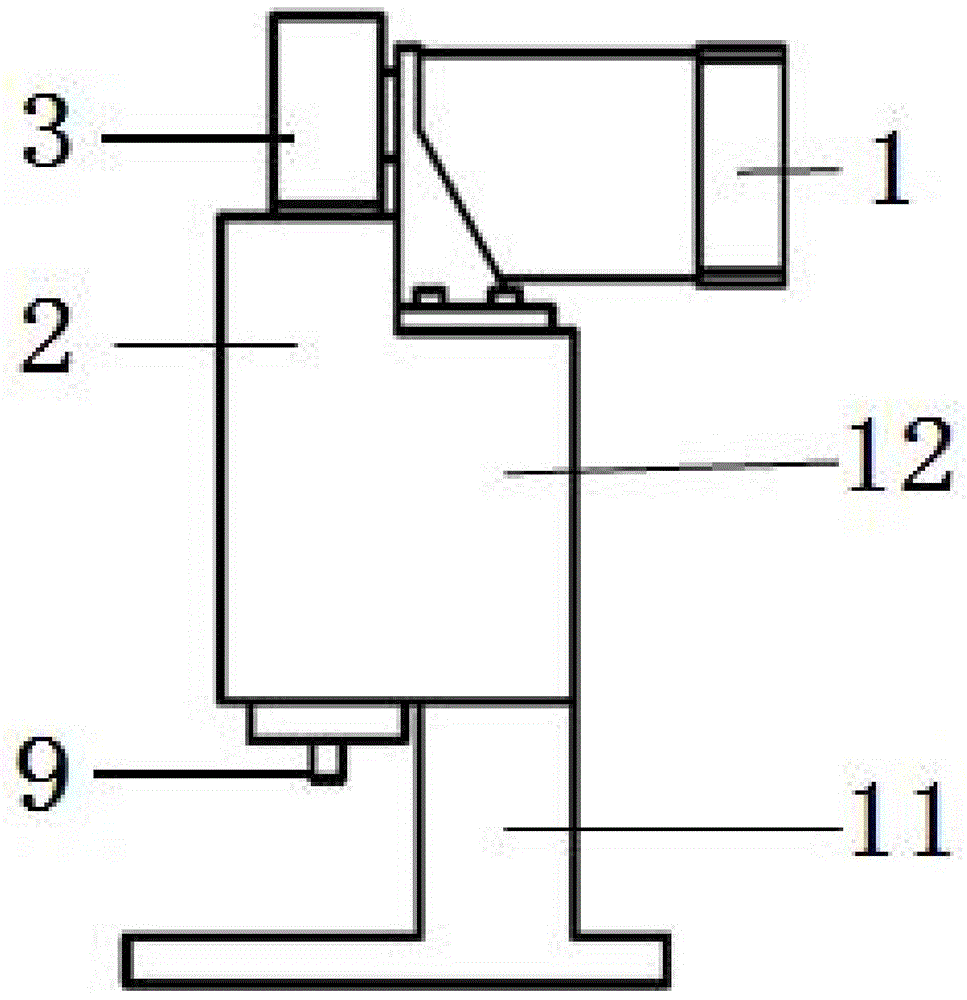
[0021] Example: Combined Figure 1~Figure 4 As shown, the high-frequency and small-load mechanical-hydraulic compound transmission press provided by the present invention consists of a servo rotary motor 1, a hydraulic cylinder 2, a form-closed eccentric mechanism 3, a piston 8, a return spring (not visible in the figure), Piston rod 9, machine tool base 11 and machine tool support frame 12 are jointly formed.

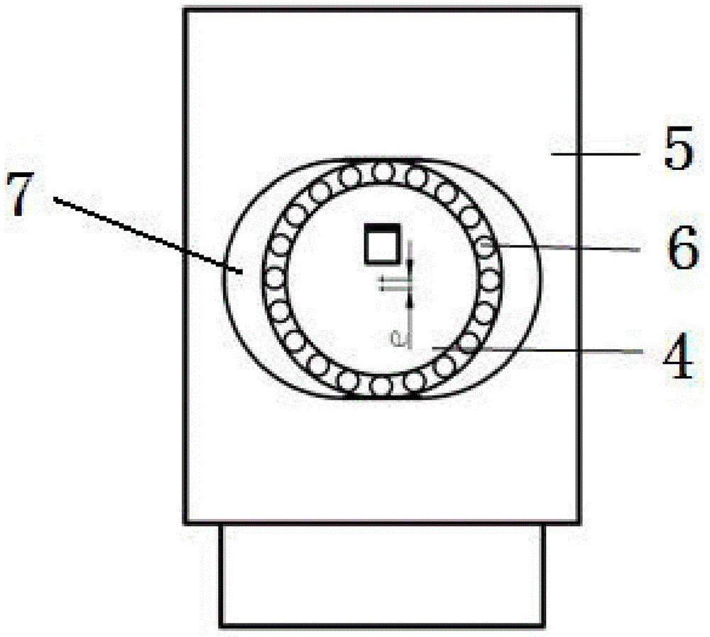
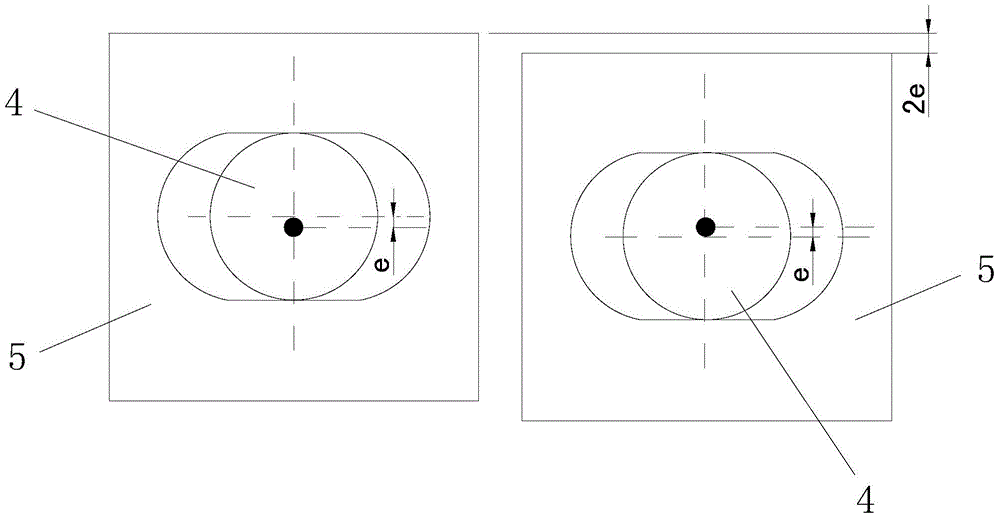
[0022] In this embodiment, the machine tool support frame 12 is fixed on the machine tool base 11 , the servo rotary motor 1 is fixed on the machine tool support frame 12 , and the hydraulic cylinder 2 is integrally connected to one side of the machine tool support frame 12 . The mechanism in this embodiment is composed of an eccentric rotating member 4 , a form closure 5 and a bearing 6 . The eccentric rotating member 4 in this embodiment is an eccentric bushing, which is sleeved and fixed on the output shaft (not shown in the figure) of the servo rotary motor 1, ...


PUM


Abstract

The invention discloses a high-frequency small-load mechanical-hydraulic compound transmission press machine which comprises a servo rotation motor and a hydraulic cylinder and is characterized by further comprising a sealed eccentric mechanism. The sealed eccentric mechanism comprises an eccentric rotary member and a form seal, wherein the eccentric rotary member and the output shaft of the servo rotation motor are fixed, and the eccentric rotary member is assembled into a driving hole of the form seal through a bearing to drive the form seal to move vertically. A piston cavity is formed in the hydraulic cylinder, a piston is arranged in the piston cavity, the lower portion of the form seal is arranged in the piston cavity and positioned above the piston, the bottom of the piston is connected with a piston rod which is positioned in a piston rod cavity, a plurality of reflowing holes for communicating the piston cavity with the piston rod cavity are formed in the piston, and a return spring is arranged between hydraulic cylinder and the position below the piston. The high-frequency small-load mechanical-hydraulic compound transmission press machine has the advantages of a mechanical press machine and a hydraulic press machine: small size, simple structure, low maintenance cost, high production efficiency and control accuracy, low device operation noise, stable work process and large operating stroke.

Description

technical field [0001] The invention relates to a high-frequency and small-load mechanical-hydraulic compound transmission press, which belongs to the technical field of presses combining machinery and hydraulic pressure. Background technique [0002] In the field of forming processing, mechanical presses and hydraulic presses are two main processing equipment. Traditional mechanical presses have high speed and high efficiency, but are bulky, lack flexibility, and have poor control accuracy (in stretching and other processes). The vibration and noise are large when the equipment is working, and it cannot meet the needs of various processing techniques. Although the hydraulic press is small in size and high in control accuracy, it is slow in speed and small in working stroke, resulting in low production efficiency, difficult system maintenance, easy oil leakage, and high maintenance costs. In addition, the oil of the traditional hydraulic press achieves speed-up through t...

Claims


Application Information

Patent Timeline
IPC IPC(8): B30B1/32
Inventor 黄颖王明娣
Owner SUZHOU UNIV
Why Eureka
Try Eureka