
Exhaust emission control device for a water vehicle and method for operating an exhaust emission control device

A technology of exhaust emission and control device, which is applied in the direction of exhaust device, muffler device, exhaust gas treatment, etc., can solve problems such as difficulty, large installation space for ships, large cost, etc., and achieves reduction of production cost, investment cost, installation space, etc. reduced effect

Active Publication Date: 2014-01-29
VTESCO TECH GMBH
View PDF4 Cites 6 Cited by
  • Summary
  • Abstract
  • Description
  • Claims
  • Application Information

AI Technical Summary

Problems solved by technology

In this case, the overall size of these exhaust gas treatment devices which are now necessary is also considered to be critical, since they occupy a considerable installation space in the vessel, and thus have to be given due consideration, even in the design The same goes for the stage, otherwise integration would have to happen afterwards, which can be difficult
At the same time, the additional need for installation space leads to considerable costs, which also had to be taken into account in the production of ships

Method used


Image

  • Exhaust emission control device for a water vehicle and method for operating an exhaust emission control device
  • Exhaust emission control device for a water vehicle and method for operating an exhaust emission control device
  • Exhaust emission control device for a water vehicle and method for operating an exhaust emission control device

Examples


Embodiment Construction

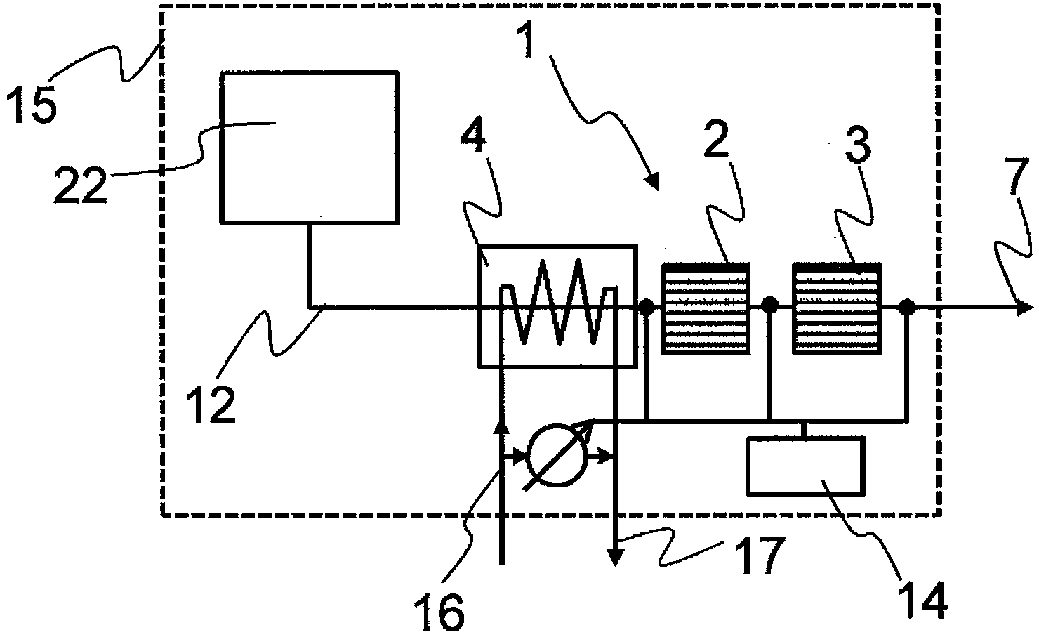
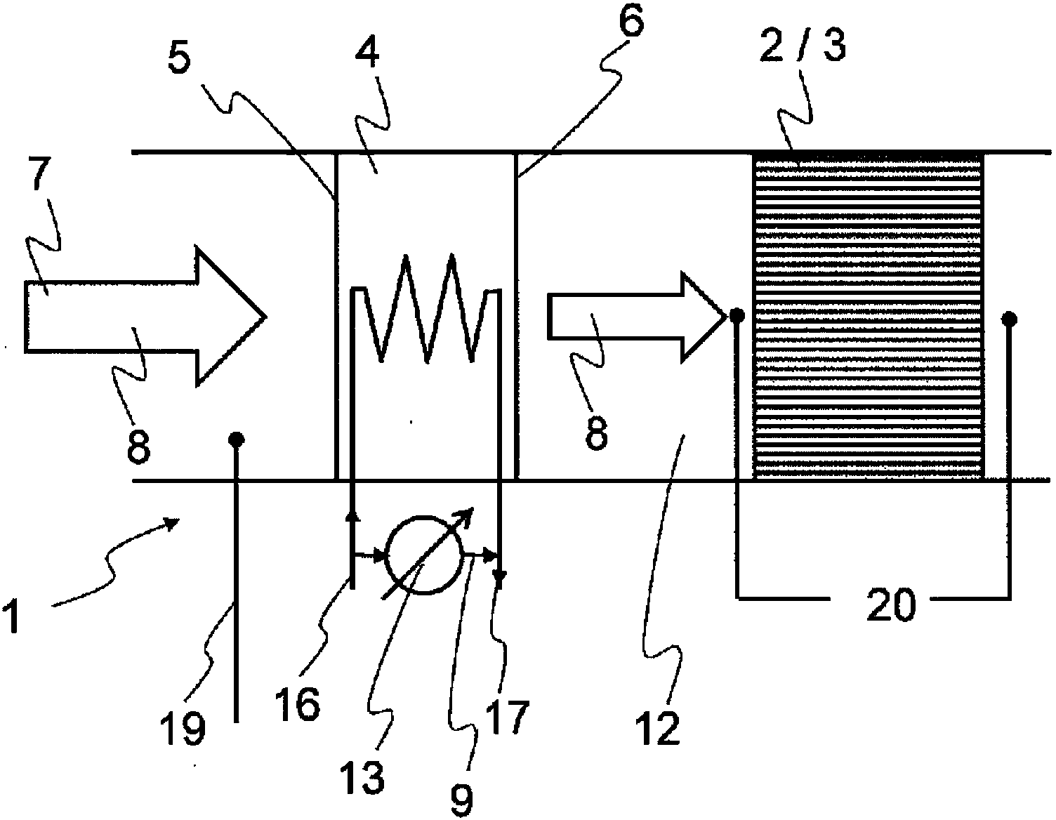
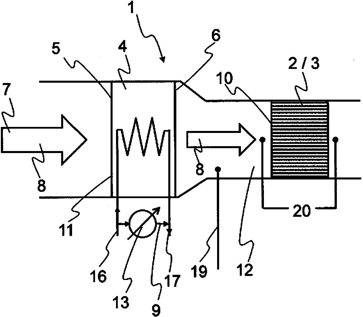
[0039] figure 1 A vessel 15 is schematically shown with a drive 22 and a discharge pipe 12 connected to the drive 22 . Exhaust pipe 12 conveys exhaust gas 7 to exhaust emission control device 1 which has heat exchanger 4 and downstream of the heat exchanger particle filter 2 and SCR catalytic converter 3 . The heat exchanger 4 comprises a cooling circuit which operates with sea water 16 as cooling medium 17 . In particular, the use of seawater heat exchangers is advantageous, since said heat exchangers are implemented as "open" circuits, in which fresh (cold) seawater is constantly supplied and heated seawater can be discharged back into seawater (via discharge line). In addition, this seawater can also be used to cool other parts of the ship, such as internal combustion engines. The exhaust emission control device 1 also includes a controller 14 which is connected to the corresponding sensor and the heat exchanger 4 in the emission line.

[0040] figure 2 A first embodi...


PUM


Abstract

An exhaust gas cleaning device for a watercraft includes at least a particle filter and / or an SCR catalytic converter and a heat exchanger disposed upstream thereof. The heat exchanger is operated with seawater as a cooling medium. The heat exchanger has an exhaust gas inlet side and an exhaust gas outlet side and is suitable for reducing a volumetric flow rate of an exhaust gas between the exhaust gas inlet side and the exhaust gas outlet side by a certain value in a certain temperature range of the exhaust gas at the exhaust gas inlet side. A watercraft and a method for operating an exhaust gas cleaning device for a watercraft are also provided.

Description

technical field [0001] The invention relates to an exhaust emission control device for a vessel and a method for operating an exhaust emission control device. Background technique [0002] As a rule, boats have large-volume internal combustion engines and correspondingly designed exhaust systems. Due to increasingly stringent permissible emission quantities involving internal combustion engines or drive units on board ships, complex exhaust emission control devices are required in many cases, even for ships. Due to the high exhaust gas throughput (volume flow / mass flow), a correspondingly bulky exhaust emission control device likewise has to be provided, which increases the costs accordingly. Suitable exhaust emission control devices, such as oxidation catalytic converters, storage units, particle filters and SCR systems (hydrolytic catalytic converters and SCR catalytic converters), on the one hand have to be large in size and on the other hand have to provide a large amou...

Claims


Application Information

Patent Timeline
Patent Type & Authority Applications(China)
IPC IPC(8): F01N3/033F01N3/20
CPCF01N2240/02Y02T10/24F01N2410/02F01N3/2066F01N2590/02F01N3/033F01N3/0205Y02A50/20Y02T10/12F01N3/20
Inventor 贝恩德·丹克特塞缪尔·沃格尔塞巴斯蒂安·拜尔
Owner VTESCO TECH GMBH
Learn More