
Mounting equipment for electronic components and its control method

A technology of electronic components and control methods, applied in the direction of electrical components, electrical components, etc., can solve the problems that the elongation of the transmission belt cannot be considered, and it is difficult to accurately control the placement equipment of electronic components, so as to reduce position errors, prolong life, The effect of improving positioning accuracy

Inactive Publication Date: 2018-04-17
HANWHA AEROSPACE CO LTD
View PDF6 Cites 0 Cited by
  • Summary
  • Abstract
  • Description
  • Claims
  • Application Information

AI Technical Summary

Problems solved by technology

However, such prior art cannot take into account the impact of the elongation of the drive belt, it does not actively reduce the generation of mechanical tolerances in the system, but compensates the final electronic components by using the existing mechanical tolerances. posture, making it difficult to precisely control electronic component placement equipment

Method used

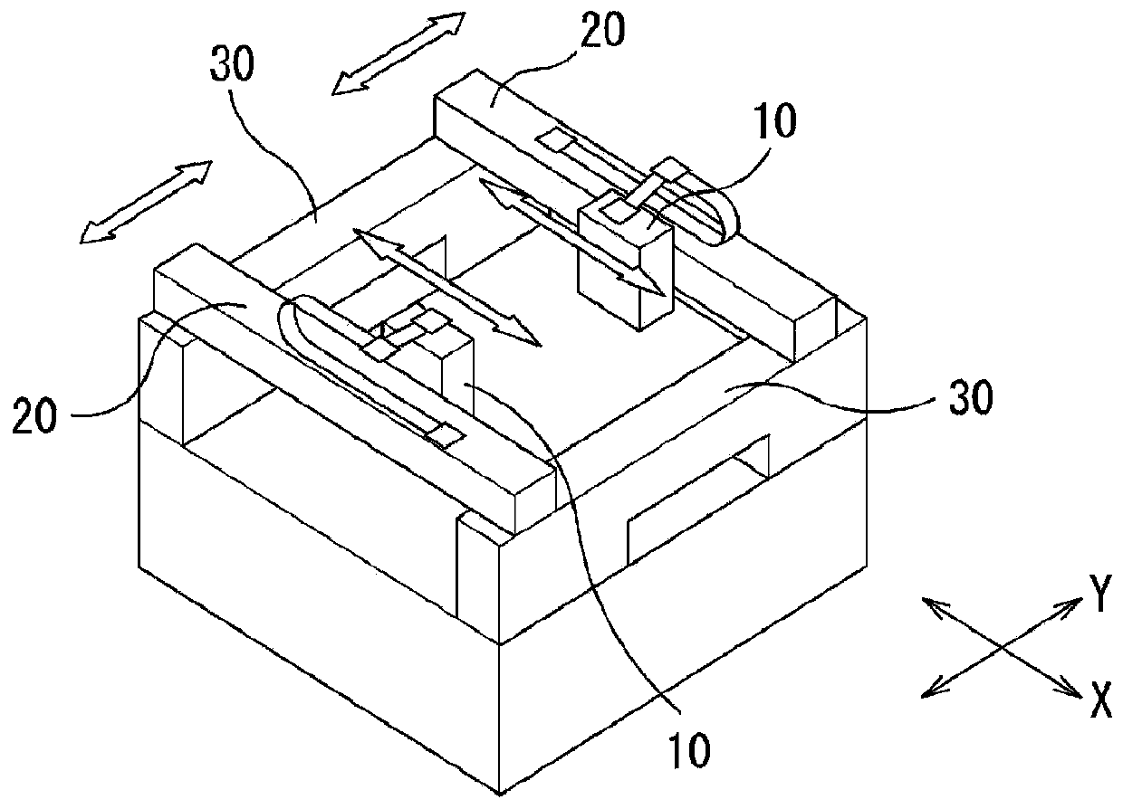
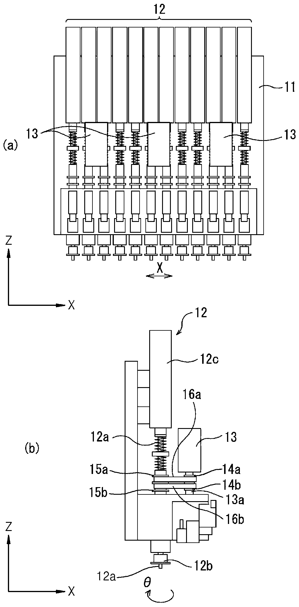
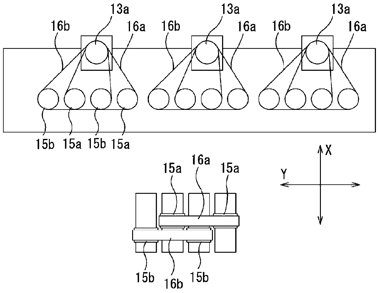

Image

  • Mounting equipment for electronic components and its control method
  • Mounting equipment for electronic components and its control method
  • Mounting equipment for electronic components and its control method

Examples


Embodiment Construction

[0059] The present invention will become clearer with reference to the accompanying drawings and specific embodiments described below. However, the present invention is not limited to the embodiments described below, which can be embodied in different ways, but this embodiment makes the disclosure of the present invention more complete. It is provided for those who fully grasp the scope of the present invention, and the present invention is defined only by the scope of the claims. On the other hand, the terms used in this specification are for describing an example, and do not limit the present invention. In this specification, unless otherwise specified in the text, the singular also includes the plural. "comprises" and / or "comprising" as used in the specification means that the mentioned components, steps, actions and / or elements do not exclude one or more other components, steps, actions and / or elements existence or addition. Terms such as first and second may be used to...


PUM


Abstract

The invention discloses electronic component mounting equipment and a control method thereof. The electronic component placement equipment of the present invention is characterized in that it includes: a placement head unit, wherein, in order to absorb electronic components and mount them on a printed circuit board, a plurality of suction nozzles are arranged in one or more rows; the driving pulley , which is attached to the driving shaft of the driving part; a driven pulley, which rotates with each suction nozzle; a transmission belt, which is wound on the driving pulley and the driven pulley, and the multiple Each suction nozzle rotates around the axis of the suction nozzle through the rotation of the driving part, and a plurality of driving pulleys are arranged on the driving shaft, and one or more driven pulleys respectively corresponding to each driving pulley Drive belts are wound, and only the inner side of each belt is in contact with the driving pulley and the one or more driven pulleys, and no fixed idler pulley is arranged in contact with the outer side of each belt.

Description

technical field [0001] The invention relates to an electronic component mounting equipment for mounting electronic components such as IC chips on a printed circuit board and a control method thereof. Background technique [0002] The placement equipment moves the electronic components from the component supply part to the printed circuit board by suctioning the head unit with the suction nozzle, and mounts them at a given position on the printed circuit board. [0003] Recently, in order to improve placement efficiency, a placement head unit equipped with a plurality of suction nozzles is often used as a placement head unit. By employing the mounting head unit as described above, a plurality of components can be mounted in one mounting cycle in which the mounting head unit goes back and forth between the component supply device and the circuit board once. [0004] Such a head unit requires a nozzle rotation drive mechanism that rotates a plurality of nozzles along the perip...

Claims


Application Information

Patent Timeline
Patent Type & Authority Patents(China)
IPC IPC(8): H05K13/04
Inventor 宫原清一田中勇次
Owner HANWHA AEROSPACE CO LTD
Learn More