Eureka AIR delivers breakthrough ideas for toughest innovation challenges, trusted by R&D personnel around the world.

Drill rod buffer positioning device of hydraulic rock drill

A technology of hydraulic rock drill and buffer device, which is applied to the driving device of rotary combined drilling, impact drilling, reciprocating drilling rig, etc. Effect

Active Publication Date: 2014-01-29
荣成中磊科技发展有限公司
View PDF5 Cites 7 Cited by
  • Summary
  • Abstract
  • Description
  • Claims
  • Application Information

AI Technical Summary

Problems solved by technology

[0004] In order to overcome the rigid connection between the drill rod and the drill shank in the prior art, it is easy to cause severe vibration and wear between the drill shank and the parts in the machine head body, and there is no axial limiter between the drill rod and the drill shank. Inconvenience, the present invention provides a drill rod buffer device for a hydraulic rock drill with simple structure, reasonable design, easy use, and fast drill replacement

Method used


Image

  • Drill rod buffer positioning device of hydraulic rock drill
  • Drill rod buffer positioning device of hydraulic rock drill
  • Drill rod buffer positioning device of hydraulic rock drill

Examples


Embodiment Construction

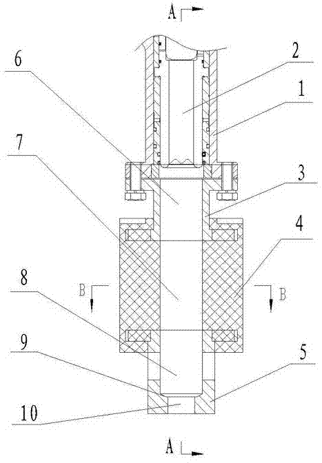
[0012] exist figure 1 Among them, a drill rod buffer device for a hydraulic rock drill, which includes a head body 1 of the rock drill and a shank 2 installed in the head body 1 for installing a drill rod.

[0013] Such as figure 1 As shown, the cross-section of the inner cavity of the shank 2 is a hexagon that coincides with the tail of the drill rod.

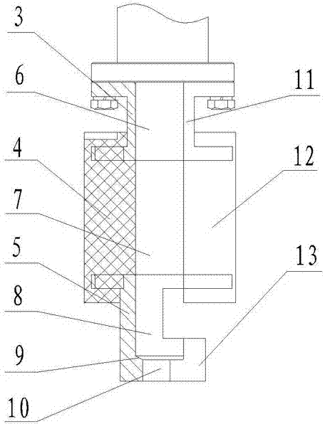
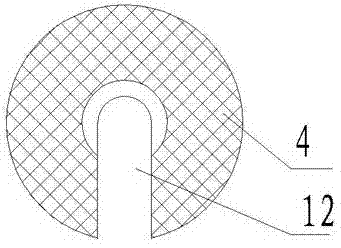
[0014] exist figure 1 Among them, a drill rod buffer device for a hydraulic rock drill, which also includes an upper coupling plate 3 , a buffer body 4 and a lower coupling plate 5 . The upper coupling disc 3 and the lower coupling disc 5 are made of metal materials, and the buffer body 4 is made of rubber or other elastic materials.

[0015] Such as figure 1 As shown, the upper end of the upper coupling disc 3 is connected to the end flange of the head body 1, the lower end of the upper coupling disc 3 is fixedly connected to one end of the buffer body 4, and the upper end of the lower coupling disc 5 is fixed to the othe...


PUM


Abstract

The invention relates to a drill rod buffer positioning device of a hydraulic rock drill. The drill rod buffer positioning device comprises a nose body of the rock drill and a drill rod tail sleeve mounted in the nose body and is characterized by further comprising an upper connecting plate, a buffer body and a lower connecting plate which are sequentially connected. The upper connecting plate is connected with a nose body flange. A through drill rod tail cavity is coaxially formed in the buffer body and the upper connecting plate. A drill rod tail cavity, a shoulder and a drill rod cavity are coaxially arranged on the lower connecting plate. An upward drill rod tail insertion groove is formed on the same side of each of the upper connecting plate, the buffer body and the lower connecting plate. The drill rod buffer positioning device has the advantages that rebound impact generated on a drill rod is absorbed by the buffer body, rigid impact among parts is avoided, and service lives of the drill rod and a machine body are prolonged; the shoulder axially limits a drill rod tail, and drill rod holding is unnecessary when the drill rod is vertical; the drill rod buffer positioning device is simple in structure, reasonable in design and simple to use.

Description

technical field [0001] The invention relates to a driving device for combined impact and rotation drilling, in particular to a drilling rod buffering and positioning device for a hydraulic rock drill. Background technique [0002] The hydraulic rock drill is a new type of rock drill that has emerged in recent years. It uses circulating high-pressure oil as the power to drive the drill rod and drill bit, and drills holes in the rock mass by means of impact rotation. Compared with pneumatic rock drills, it has many advantages such as less energy consumption, fast rock drilling speed, high efficiency, low noise, easy control, less drill stuck accidents, and long life of drilling tools. It has developed rapidly in recent years. [0003] The hydraulic rock drill is mainly composed of two parts: the impact mechanism and the slewing mechanism. The impact mechanism is composed of cylinder, piston, reversing valve, accumulator and other main components. Through the reversing of the ...

Claims


Application Information

Patent Timeline
Patent Type & Authority Applications(China)
IPC IPC(8): E21B1/26E21B6/08
Inventor 刘新刚刘建维
Owner 荣成中磊科技发展有限公司
Why Eureka
Eureka Blog
Learn More