Combined water cooling plate

A water-cooled plate and combined technology, which is applied in the direction of cooling/ventilation/heating transformation, etc., can solve the problems of water-cooled plate leakage, high welding cost, and failure to meet the use requirements, so as to reduce processing costs, improve safety, and facilitate normal operation. The effect of work

Active Publication Date: 2015-11-18
CRRC DALIAN INST CO LTD
View PDF3 Cites 0 Cited by
  • Summary
  • Abstract
  • Description
  • Claims
  • Application Information

AI Technical Summary

Problems solved by technology

[0003] In response to the above problems, the present invention researches and designs a combined water-cooled plate to solve the safety hazard of leakage in the existing brazed water-cooled plate to a certain extent. At the same time, the welding cost is very high and cannot meet people’s needs. Disadvantages of using requirements

Method used


Image

  • Combined water cooling plate
  • Combined water cooling plate
  • Combined water cooling plate

Examples


Embodiment 1

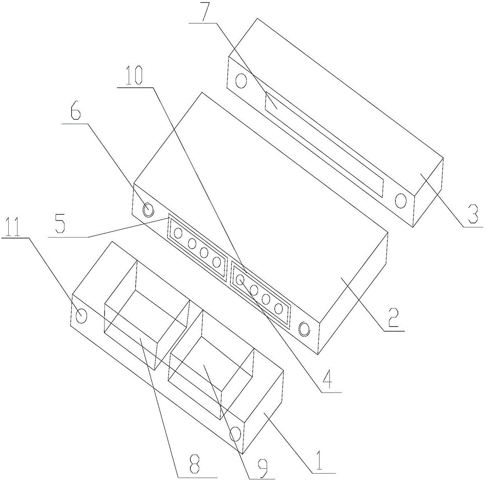
[0021] Example 1, such as Figure 1-Figure 5 As shown, a combined water-cooled plate includes: collecting chamber I1, main cavity 2 and collecting chamber II3; one end of the main cavity 2 is provided with collecting chamber I1, and the other end is provided with collecting chamber II3, It is characterized in that: the collecting chamber I1, the main chamber body 2 and the collecting chamber II3 of the separate structure are fastened together by bolts passing through the through hole 11, and realize rapid assembly and make samples; in order to ensure normal operation and On the premise of prolonging the working life, the high cost of brazing is avoided. This structure can conveniently adjust the channel arrangement according to different working conditions such as different heat dissipation and resistance requirements, and the two collecting chambers can be combined with different main The cavity is combined to realize the modular production of the water-cooled plate, which ov...

Embodiment 2

[0024] Example 2, such as Figure 1-Figure 5 As shown, a combined water-cooled plate includes: collecting chamber I1, main cavity 2 and collecting chamber II3; one end of the main cavity 2 is provided with collecting chamber I1, and the other end is provided with collecting chamber II3, It is characterized in that: the collecting chamber I1, the main chamber body 2 and the collecting chamber II3 of the separate structure are fastened together by studs, and two threaded holes 6 are respectively opened at the opposite ends of the main chamber body 2 , the threaded holes 6 on each side are respectively connected with the through-holes 11 on the collecting chamber I1 and collecting chamber II3 through studs for fastening and installation, which is convenient for installation and disassembly. According to the heat of the water cooling plate It is more convenient to change the layout of channel 4 according to the requirements of resistance, flow resistance and installation space, an...


PUM


Abstract

The invention discloses a combined water cooling plate. The combined water cooling plate comprises a flow collecting chamber I, a main cavity and a flow collecting chamber II, wherein one end of the main cavity is provided with the flow collecting chamber I, and the other end is provided with the flow collecting chamber II. The combined water cooling plate is characterized in that the flow collecting chamber I, the main cavity and the flow collecting chamber II with split single structures are tightly connected together through bolts penetrating through holes. The combined water cooling plate comprising the flow collecting chamber I, the main cavity and the flow collecting chamber II with split single structures can be quickly designed and manufactured according to different heat dissipation requirements of electronic power elements, and can realize quick assembly and sample production; the high cost in brazing is avoided under the premises of guaranteeing normal operation and prolonging service life; the flow collecting chamber I, the main cavity and the flow collecting chamber II are tightly connected through studs or bolts; the channel arrangement can be conveniently regulated according to different working condition requirements, so that the difficulty of high cost is overcome.

Description

technical field [0001] The invention relates to the field of water-cooled plates used for heat dissipation of power electronic products, and relates to a water-cooled plate. Background technique [0002] At present, the working mode of the water-cooled plate is: the heat generated by the power module is transferred to the outer surface of the main cavity through its installation contact surface in the form of heat conduction, and then the heat is diffused from the outer surface of the main cavity to the inner surface of the main cavity in the form of heat conduction, and finally The heat is transferred from the water-cooled plate to the external environment by means of convective heat exchange. When the entire system reaches thermal equilibrium, the surface temperature of the main cavity will remain at the normal operating temperature of the power module. There is a problem: as the electronic components With the rapid development of high-power and high-integration devices, t...

Claims


Application Information

Patent Timeline
Patent Type & Authority Patents(China)
IPC IPC(8): H05K7/20
Inventor 王硕苗苗李雪冬
Owner CRRC DALIAN INST CO LTD
Why Eureka
Try Eureka