
Support structure for planar reflection mirror on movement platform

A technology for plane mirrors and support structures, applied in installation, optics, instruments, etc., can solve the problems of increasing load weight and volume, not being able to guarantee the surface shape error of plane mirrors, and not being able to adapt to support methods, etc., to achieve the effect of reliable support

Active Publication Date: 2014-01-22
INST OF OPTICS & ELECTRONICS - CHINESE ACAD OF SCI
View PDF3 Cites 9 Cited by
  • Summary
  • Abstract
  • Description
  • Claims
  • Application Information

AI Technical Summary

Problems solved by technology

[0002] In order to ensure the imaging quality, the surface shape accuracy requirements in the optical system are often high, especially for the surface shape of the mirror; for small-diameter flat mirrors, the surface shape requirements can be guaranteed by using the back edge support method. For large-caliber reflectors, flexible support is currently the main support method. For planar reflectors in the optical system on the moving platform, flexible support can ensure the surface shape requirements, but the flexible support platform requires high rigidity. Otherwise, the deformation of the mounting platform will be transmitted to the flat mirror through the flexible support, and the mounting platform with high rigidity and flexible support means that the load weight and volume will be increased
In the vibration environment, the requirements of the surface error of the plane mirror cannot be guaranteed, and the support method that cannot adapt to the vibration environment

Method used


Image

  • Support structure for planar reflection mirror on movement platform
  • Support structure for planar reflection mirror on movement platform
  • Support structure for planar reflection mirror on movement platform

Examples


Embodiment Construction

[0019] In order to make the object, technical solution and advantages of the present invention clearer, the present invention will be described in further detail below in conjunction with specific embodiments and with reference to the accompanying drawings.

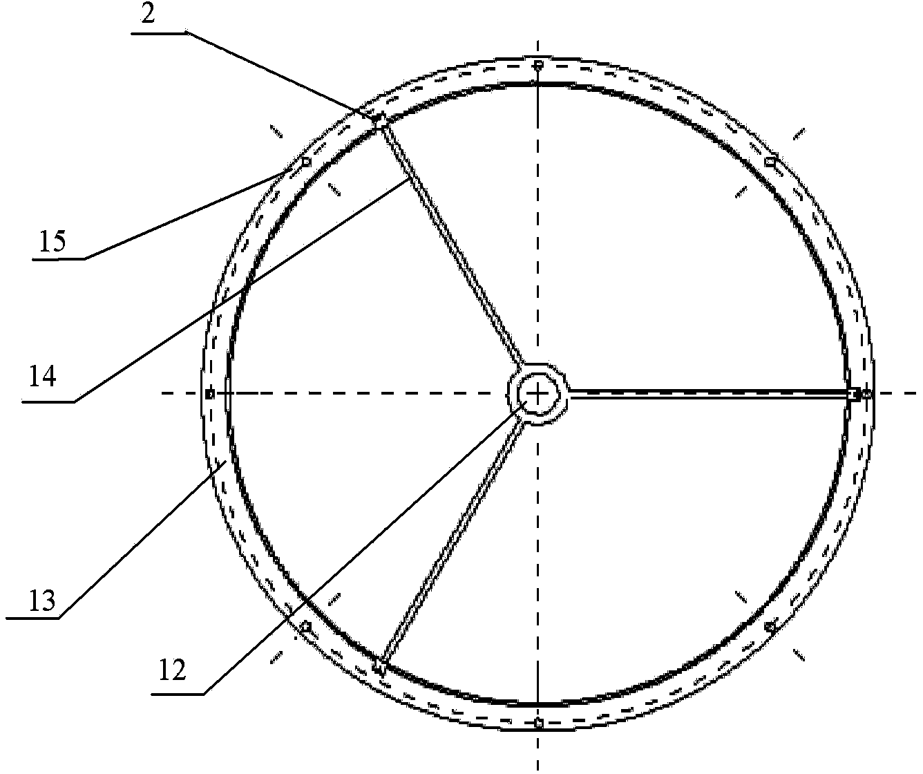
[0020] Such as figure 1 with Figure 10 Shown is the supporting structure of the flat mirror 9 on the moving platform, which mainly consists of a flange ring 1, a pressing block 2, a sleeve 3, a top plate 4, a locking ring 5, a ball head rod 6, a linear motor 7, and a plurality of screws 8 It is composed of a plane reflector 9; the back of the plane reflector 9 is supported on the flange ring 1 by edge support, and the plane reflector 9 is pressed by a plurality of pressing blocks 2, and the pressing blocks 2 are fixed on the flange by screws 8 on the ring 1; the sleeve 3 is fixed on the back of the plane reflector 9 by gluing, and the top plate 4 is fixedly connected with the sleeve 3 by screws; Tighten the ball stud 6...


PUM


Abstract

The invention belongs to a support structure for a planar reflection mirror on a movement platform. The support structure is formed by a flange ring, pressure blocks, a sleeve, a top plate, a locking ring, a ball head rod and a linear motor; the back of the planar reflection mirror is supported on the flange ring by an edge supporting mode; the planar reflection mirror is pressed by the multiple pressure blocks fixed on the flange ring; the sleeve is fixed at the back of the planar reflection mirror; the top plate is fixedly connected with the sleeve; one end of the ball head rod is supported on the top plate; the ball head rod is locked by the locking ring; the other end of the ball head rod is connected with the linear motor fixed on the flange ring. The support structure for the planar reflection mirror on the movement platform is suitable for supporting the planar reflection mirror in an optical instrument on the movement platform.

Description

technical field [0001] The invention relates to a support structure for a plane reflector on a moving platform, specifically, to ensure that the surface shape error of the plane reflector meets the requirements under the vibration and impact environment of the moveable platform. Background technique [0002] In order to ensure the imaging quality, the requirements for surface shape accuracy in the optical system are often high, especially for the surface shape of the mirror; for small-diameter flat mirrors, the surface shape requirements can be guaranteed by using the back edge support method, For large-caliber mirrors, flexible support is currently the main support method. For planar mirrors in the optical system on a moving platform, flexible support can ensure the surface shape requirements, but the flexible support platform requires high rigidity. Otherwise, the deformation of the mounting platform will be transmitted to the flat mirror through the flexible support, and ...

Claims


Application Information

Patent Timeline
Patent Type & Authority Applications(China)
IPC IPC(8): G02B7/198G02B7/192G02B7/185
Inventor 刘兴法扈宏毅温正明刘儒贞包启亮
Owner INST OF OPTICS & ELECTRONICS - CHINESE ACAD OF SCI
Learn More