
Device and method for testing whether camera module is qualified

A camera module and pixel point technology, which is applied in the direction of testing optical performance, etc., can solve the problems of adjusting time and affecting the test efficiency of camera modules, and achieve the effects of shortening time, improving test efficiency, and high degree of programming

Active Publication Date: 2016-05-11
GUANGZHOU SHIRUI ELECTRONICS
View PDF6 Cites 0 Cited by
  • Summary
  • Abstract
  • Description
  • Claims
  • Application Information

AI Technical Summary

Problems solved by technology

[0007] Although the above methods can be used to test whether the camera modules are qualified, each camera module needs to be adjusted during the test, and the adjustment takes a long time. It takes no less than 1 minute to test each camera module, which is serious. Affected the test efficiency of the camera module

Method used


Image

  • Device and method for testing whether camera module is qualified
  • Device and method for testing whether camera module is qualified
  • Device and method for testing whether camera module is qualified

Examples


Embodiment 1

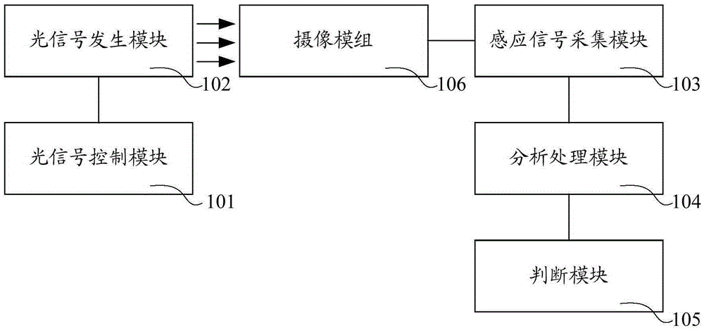
[0027] This embodiment provides a device for testing whether the camera module is qualified, such as figure 1 As shown, the device includes: an optical signal control module 101, an optical signal generation module 102, an induction signal acquisition module 103, an analysis processing module 104, and a judgment module 105;

[0028] The optical signal control module 101 is connected to the optical signal generation module 102, and controls the optical signal generation module 102 to provide optical signals for the photosensitive chip 301 of the camera module 106;

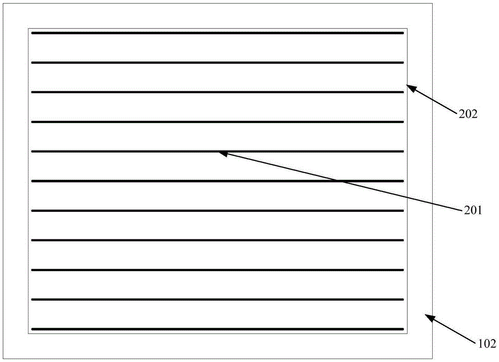
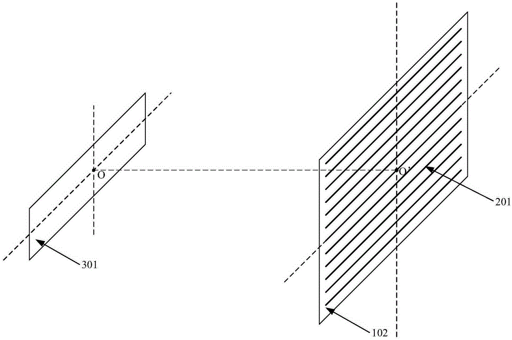
[0029] Such as figure 2 As shown, the optical signal generating module 102 includes a plurality of light-emitting units 201 arranged in a grid shape, and the multiple light-emitting units 201 are all strip-shaped structures, which are parallel to each other, evenly spaced, and arranged at the same end flush. On the plane, a rectangular light-emitting area 202 is formed, such as image 3 As shown, the light-emitting area ...

Embodiment 2

[0044] This embodiment provides a method for testing whether a camera module is qualified. The method is used in the device described in Embodiment 1. The method includes:

[0045] Step S71: Place a camera module on one side of the light signal generating module, make the light emitting area of ​​the light signal generating module and the photosensitive chip of the camera module parallel and the centers of the two are on the same straight line, and make The multiple light emitting units of the light signal generating module are parallel to the long sides of the photosensitive chip, the light signal generating module is connected with the light signal control module, and the camera module and the sensing signal are collected Module connection;

[0046] Step S72: using the light signal control module to control the light signal generating module to turn on each light emitting unit of the light signal generating module once to provide the light signal to the photosensitive chip;

[004...


PUM


Abstract

The invention provides device and a method for testing whether a camera module is qualified or not. An optical signal generation module is arranged in a direction which a camera module plane faces; the optical signal generation module comprises a plurality of light emitting units which are arranged in a grid structure; and the plurality of the light emitting units are parallel to one another and spaced uniformly, and end parts of the light emitting units are flush with one another. During testing, a light emitting region formed by the light emitting units is parallel to a camera module light sensitive chip, and centers of the light emitting region and the camera module light sensitive chip are located on the same straight line; the light emitting units are parallel to a long side of the light sensitive chip; the plurality of the light emitting units are controlled to be switched on for one time; in the process, data of each pixel sensing signal of the light sensitive chip are collected, analyzed and processed, and a pitch angle of each pixel and a left inclined angle and a right inclined angle of the camera module are obtained; and finally, whether the camera module is qualified or not is judged according to a specified preset range. The method is used for testing whether the camera module is qualified or not, the position of the camera module is not required to be adjusted manually, the time spent in testing the camera module is greatly shortened, and the testing efficiency is improved.

Description

Technical field [0001] The invention relates to the technical field of camera modules, and more specifically, to a device and method for testing whether a camera module is qualified. Background technique [0002] The optical touch screen has the advantages of portability, high accuracy, and fast response speed. It can be used in conference venues, commercial display venues, education and training venues, exhibitions, financial industry, military and many fields. [0003] The core component of the optical touch screen is the camera module. The commonly used camera module in the optical touch screen is the linear camera module. The photosensitive chip plane of this camera module is rectangular, and the photosensitive chip has a row of pixels side by side along the long side. Different camera modules have different numbers of pixels. Ideally, this row of pixels is on the axis of symmetry along the long side of the photosensitive chip, so as to ensure that each pixel receives light wi...

Claims


Application Information

Patent Timeline
Patent Type & Authority Patents(China)
IPC IPC(8): G01M11/02
Inventor 谢旺
Owner GUANGZHOU SHIRUI ELECTRONICS
Learn More