
Discharging buffering device for paper products after high-speed cutting

A buffer device and paper product technology, applied in thin material handling, transportation and packaging, sending objects, etc., can solve the problems affecting continuous production, low-speed paper feeding can not match, etc., to achieve the effect of smooth movement

Active Publication Date: 2014-01-22
QINGDAO JINYE PRECISION MACHINERY
View PDF9 Cites 6 Cited by
  • Summary
  • Abstract
  • Description
  • Claims
  • Application Information

AI Technical Summary

Problems solved by technology

[0003] The invention aims to solve the technical problem that the high-speed paper feeding cannot match the low-speed paper feeding required by the follow-up process after the cutting speed of the paper product cutting machine reaches a certain height, which affects continuous production, and provides a high-speed paper product cutting machine that adjusts the paper feeding speed and coordinates Discharge buffer device for high-speed cutting of paper products in subsequent processes

Method used


Image

  • Discharging buffering device for paper products after high-speed cutting
  • Discharging buffering device for paper products after high-speed cutting

Examples


Embodiment Construction

[0013] Description with reference to the accompanying drawings.

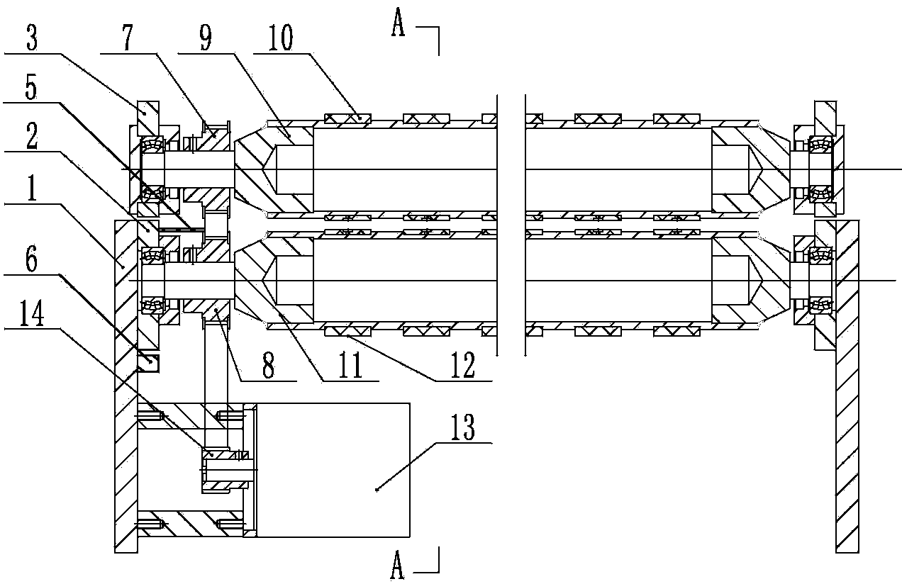
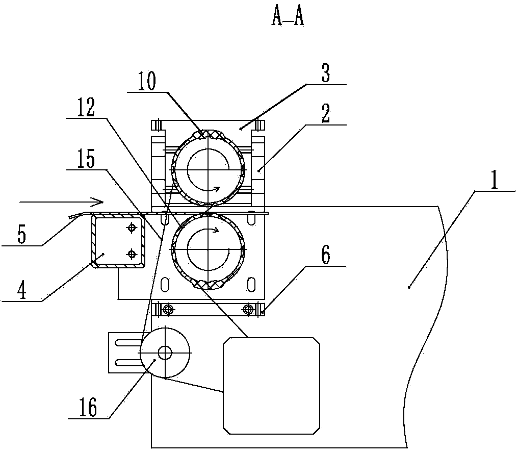
[0014] The outer surfaces of the two lower shaft mounting plates 2 are in contact with the inner surfaces of the two wall panels 1 , and the two vertical wall panels 1 are parallel to each other. The two ends of the cross brace 4 are fixed on the inner side surfaces of the lower shaft mounting plates 2 on both sides. There are two rows of four elongated holes on the lower shaft mounting plate 2, see figure 2 , the bolt passes through the elongated hole, screwed into the screw hole on the wallboard 1, and connects the lower shaft mounting plate 2 with the wallboard 1. The adjustment block 6 of the lower shaft adjustment mechanism is fixed on the wallboard 1 and is located below the lower shaft installation plate 2 . The adjusting bolt passes through the vertical screw holes on the left and right sides of the adjusting block, and its end is in contact with the lower end surface of the lower shaft mounting plate...


PUM


Abstract

The invention provides a discharging buffering device for paper products after high-speed cutting, and belongs to a speed regulating device in a high-speed output process for the paper products. The discharging buffering device is used for reducing the paper conveying speed after the paper products are cut through a cutting machine and enabling the paper conveying speed to be matched with low-speed paper conveying required by a subsequent procedure. According to the discharging buffering device, an upper shaft rubber sleeve and a lower shaft rubber sleeve are fixedly installed on an upper rotating shaft and a lower rotating shaft in a sleeved mode respectively, the upper shaft rubber sleeve and the lower shaft rubber sleeve are located above and below the cut paper products, and the upper rotating shaft and the lower rotating shaft rotate in the reverse direction. When an outer circular protrusion of the upper shaft rubber sleeve and an outer circular protrusion of the lower shaft rubber sleeve are oppositely overlapped, the cut paper products are clamped, the linear speed of the contact portions between the outer circular protrusions and the cut paper products is greatly less than the speed of the cut paper products, and the directions of the speeds are the same. According to the technical scheme, the technical problems that high-speed paper conveying of the paper products cut through the high-speed paper cutting machine cannot be matched with low-speed paper conveying required by the subsequent procedure, and continuous production is affected are solved.

Description

technical field [0001] The invention belongs to a speed adjusting device in the high-speed output process after high-speed cutting of paper products, in particular to a high-speed cutting and discharging buffer device for paper products. Background technique [0002] Due to the increase of the cutting speed of the paper product cutting machine, in order to ensure that the cut paper product does not hinder the output of the next paper product to be cut, the paper feeding speed after the paper product is cut is accelerated, forming a high-speed paper feeding section. When the input of the follow-up process requires a relatively low paper feed speed, the high-speed paper feed after the paper product is cut cannot match the low-speed paper feed required by the follow-up process, which affects continuous production. The high-speed cutting machine in production is connected with the subsequent paper unloading and stacking process. In order to achieve the high-speed operation of t...

Claims


Application Information

Patent Timeline
IPC IPC(8): B65H29/20B65H29/68
Inventor 宋冬冬宋宝三周淼
Owner QINGDAO JINYE PRECISION MACHINERY
Learn More