Wireless transmission method, device and system
A wireless transmission and transmission delay technology, applied in the field of communication, can solve problems such as failure to meet the radio frequency specification requirements of base stations, and achieve the effect of ensuring demodulation performance
- Summary
- Abstract
- Description
- Claims
- Application Information
AI Technical Summary
Problems solved by technology
Method used
Image
Examples
Embodiment 1
[0059] This embodiment provides a wireless transmission method for carrier aggregation.
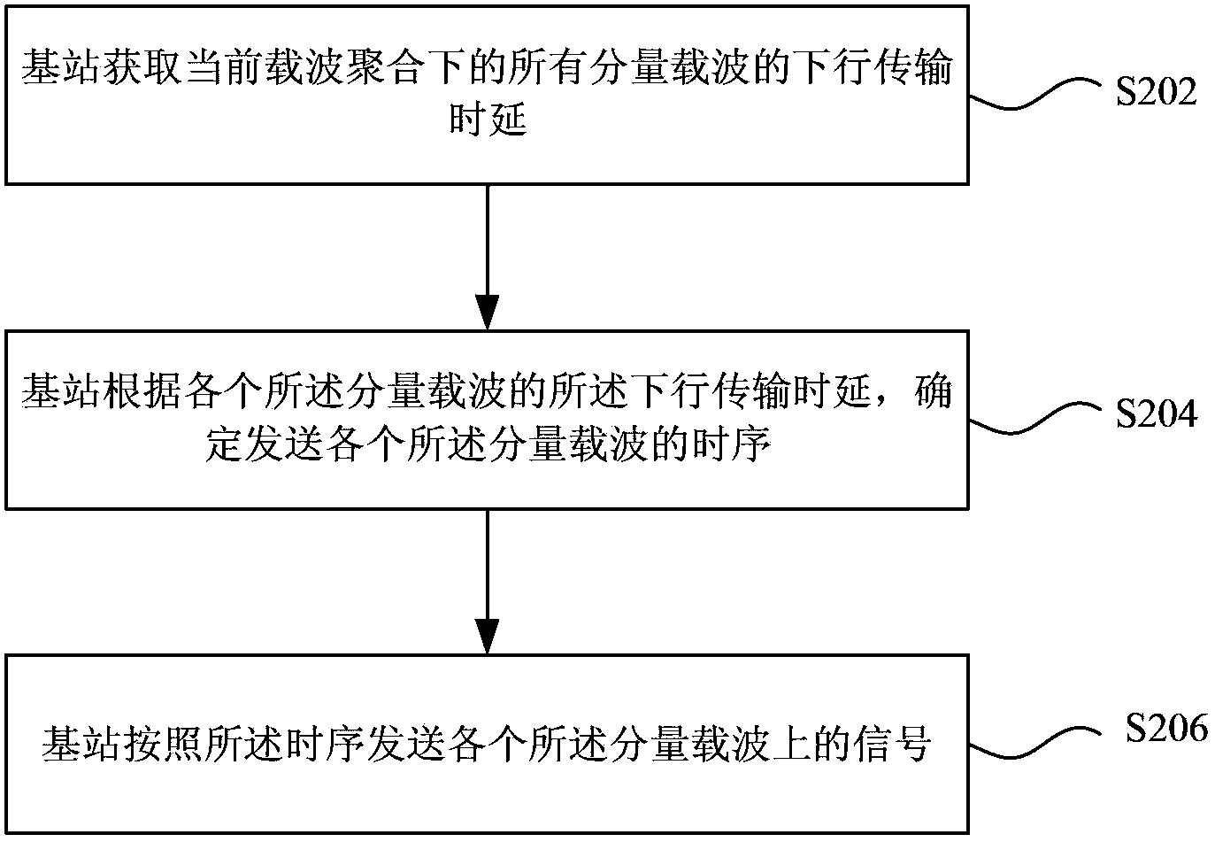
[0060] figure 2 is a flowchart of a wireless transmission method according to an embodiment of the present invention, such as figure 2 As shown, the method mainly includes the following steps:
[0061] Step S202, the base station acquires downlink transmission delays of all component carriers under the current carrier aggregation;
[0062] Step S204, the base station determines the timing of sending each of the component carriers according to the downlink transmission delay of each of the component carriers, wherein the timing can ensure that the maximum time difference between the component carriers received by the terminal is less than predetermined threshold;
[0063] Step S206, the base station sends signals on each of the component carriers according to the timing.
[0064] Through the above method provided by this embodiment, the base station determines the timing of sending e...
Embodiment 2
[0083] This embodiment provides a wireless transmission method for a wireless transmission system including a relay base station.
[0084] Figure 5 It is a flowchart of a wireless transmission method according to an embodiment of the present invention, such as Figure 5 As shown, the method includes the following steps:
[0085] Step S502, the control base station obtains the downlink transmission delay of the first carrier of the control base station, and the downlink transmission delay of the second carrier of the relay base station;
[0086] In this embodiment, both the first carrier and the second carrier may include one or more carriers.
[0087] Step S504, the controlling base station determines the first timing for the controlling base station to transmit the first carrier and the time sequence for the relay base station to transmit the first carrier according to the downlink transmission delay of the first carrier and the downlink transmission delay of the second ca...
Embodiment 3
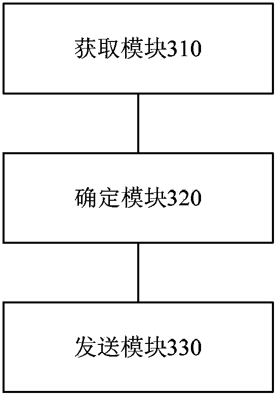
[0111] Figure 9 It is a schematic diagram of the composition of the wireless transmission system under carrier aggregation in this embodiment, as shown in Figure 9 As shown, the system includes a base station 901 and a terminal 902, wherein the base station 901 includes: a terminal transmission advance estimation module 903 (equivalent to image 3 The acquisition module 310 in, or Figure 4 In the estimation module 312) and the base station transmission time control module 904 (equivalent to image 3 The determination module 320 and the sending module 330 in ). In this system, the terminal transmission advance estimation module 903 estimates the TA of each component carrier, and then the base station transmission time control module 904 calculates the timing information sent by the base station for each component carrier, and transmits each component according to this timing information The signal on the carrier to ensure that the maximum time difference between the compo...
PUM
 Abstract
Description
Claims
Application Information
 - Generate Ideas
- Intellectual Property
- Life Sciences
- Materials
- Tech Scout
- Unparalleled Data Quality
- Higher Quality Content
- 60% Fewer Hallucinations
Browse by: Latest US Patents, China's latest patents, Technical Efficacy Thesaurus, Application Domain, Technology Topic, Popular Technical Reports.
© 2025 PatSnap. All rights reserved.Legal|Privacy policy|Modern Slavery Act Transparency Statement|Sitemap|About US| Contact US: help@patsnap.com


