A method and device for processing channel quality information
An information processing method and technology for channel quality information, applied in wireless communication, diversity/multi-antenna systems, transmission monitoring, etc., can solve problems such as channel mismatch, affecting terminal demodulation performance, etc., to ensure demodulation performance and improve network. The effect of capacity
- Summary
- Abstract
- Description
- Claims
- Application Information
AI Technical Summary
Problems solved by technology
Method used
Image
Examples
no. 1 example
[0077] In the first embodiment, it is assumed that the cell is divided into 7 prefabricated beam coverages according to the DOA range, and the numbers are respectively 0-6.
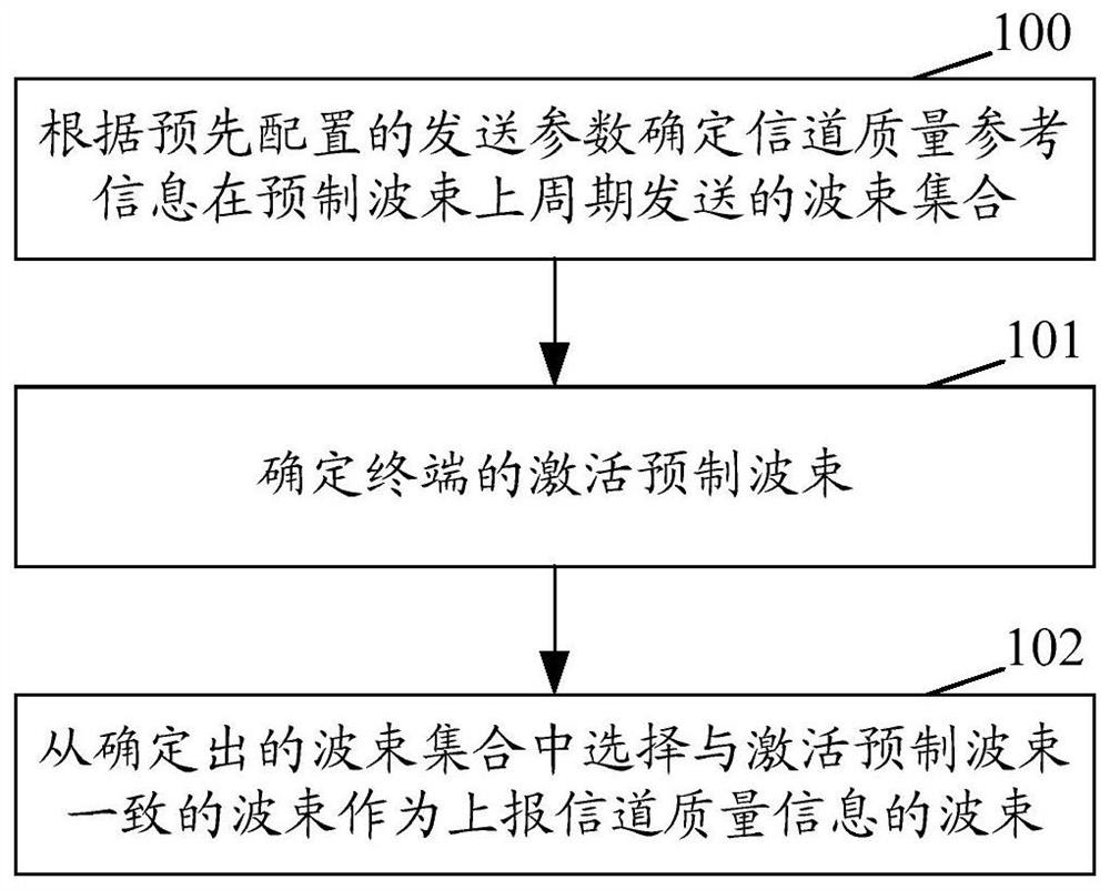
[0078] On the one hand, the CSI-RS sending subframe is calculated according to the configured sending parameters for sending the CSI-RS, wherein the configuration parameters of the CSI-RS include: sending period I CSI-RS and the offset Δ within the period CSI-RS .
[0079] In the first embodiment, it is assumed that I CSI-RS The value is 5, Δ CSI-RS The value is 1, and the calculation can be obtained: the wireless frame number (FrameNo CSI-RS ) is 0, the subframe number (SubFrameNo CSI-RS ) is 1 when the CSI-RS signal is sent, and the next time the CSI-RS signal is sent is that the radio frame number is 0, and the subframe number is 6, and so on, every 1 CSI-RS The CSI-RS signal is sent at a period such as 5ms.
[0080] In the first embodiment, the number of prefabricated beams BF NUM is 7 beams, n...
no. 2 example
[0089] In the second embodiment, it is assumed that the cell is divided into 7 prefabricated beam coverages according to the DOA range, and the numbers are respectively 0-6.
[0090] On the one hand, the CSI-RS sending subframe is calculated according to the configured sending parameters for sending the CSI-RS, wherein the configuration parameters of the CSI-RS include: a sending period I CSI-RS and the offset Δ within the period CSI-RS .
[0091] In the second embodiment, it is assumed that I CSI-RS The value is 10, Δ CSI-RS If the value is 2, it is calculated that the CSI-RS signal is sent when the radio frame number is 0 and the subframe number is 2, and the next time the CSI-RS signal is sent is when the radio frame number is 1 and the subframe number is 2, and so on. every I CSI-RS The CSI-RS signal is sent at a period such as 10ms.
[0092] In the second embodiment, the number of prefabricated beams BF NUM is 7 beams, numbered 0-6, and the CSI-RS signals are corres...
no. 3 example
[0099] In the third embodiment, it is assumed that the cell is divided into 11 prefabricated beam coverages according to the DOA range, and the numbers are respectively 0-10.
[0100] On the one hand, the CSI-RS sending subframe is calculated according to the configured sending parameters for sending the CSI-RS, wherein the configuration parameters of the CSI-RS include: a sending period I CSI-RS and the offset Δ within the period CSI-RS .
[0101] In the third embodiment, it is assumed that I CSI-RS The value is 5, Δ CSI-RS If the value is 1, it is calculated that: when the radio frame number is 0, and the subframe number is 1, the CSI-RS signal is sent, and the next time the CSI-RS signal is sent is when the radio frame number is 0, and the subframe number is 6, and so on. every I CSI-RS The CSI-RS signal is sent at a period such as 5ms.
[0102] In the third embodiment, the number of prefabricated beams BF NUM is 11 beams, numbered 0-10. In this embodiment, the CSI-RS...
PUM
 Abstract
Description
Claims
Application Information
 - R&D
- Intellectual Property
- Life Sciences
- Materials
- Tech Scout
- Unparalleled Data Quality
- Higher Quality Content
- 60% Fewer Hallucinations
Browse by: Latest US Patents, China's latest patents, Technical Efficacy Thesaurus, Application Domain, Technology Topic, Popular Technical Reports.
© 2025 PatSnap. All rights reserved.Legal|Privacy policy|Modern Slavery Act Transparency Statement|Sitemap|About US| Contact US: help@patsnap.com


