
Super surface lens antenna based on optical transformation and manufacturing method of super surface lens antenna

An optical conversion and metasurface technology, applied in the microwave field, can solve the problems of high loss, difficult fabrication, unfavorable feeding and integration of arc-shaped focusing plane, and achieve the effect of reducing volume, good feeding and integration

Active Publication Date: 2014-01-15
SOUTHEAST UNIV
View PDF6 Cites 22 Cited by
  • Summary
  • Abstract
  • Description
  • Claims
  • Application Information

AI Technical Summary

Problems solved by technology

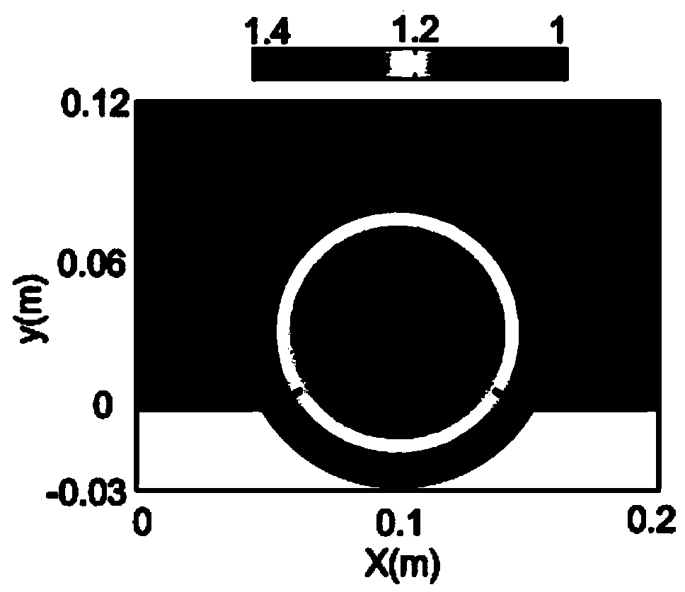
[0002] like figure 1 As shown, the existing Luneburg lens is placed in a rectangular area, wherein a part of the Luneburg lens is outside the rectangle, and the curved focusing surface of the Luneburg lens is not conducive to feeding and integration. On the other hand, the traditional spherical Lunberg lenses also have the problems of high loss and difficulty in making

Method used


Image

  • Super surface lens antenna based on optical transformation and manufacturing method of super surface lens antenna
  • Super surface lens antenna based on optical transformation and manufacturing method of super surface lens antenna
  • Super surface lens antenna based on optical transformation and manufacturing method of super surface lens antenna

Examples


Embodiment Construction

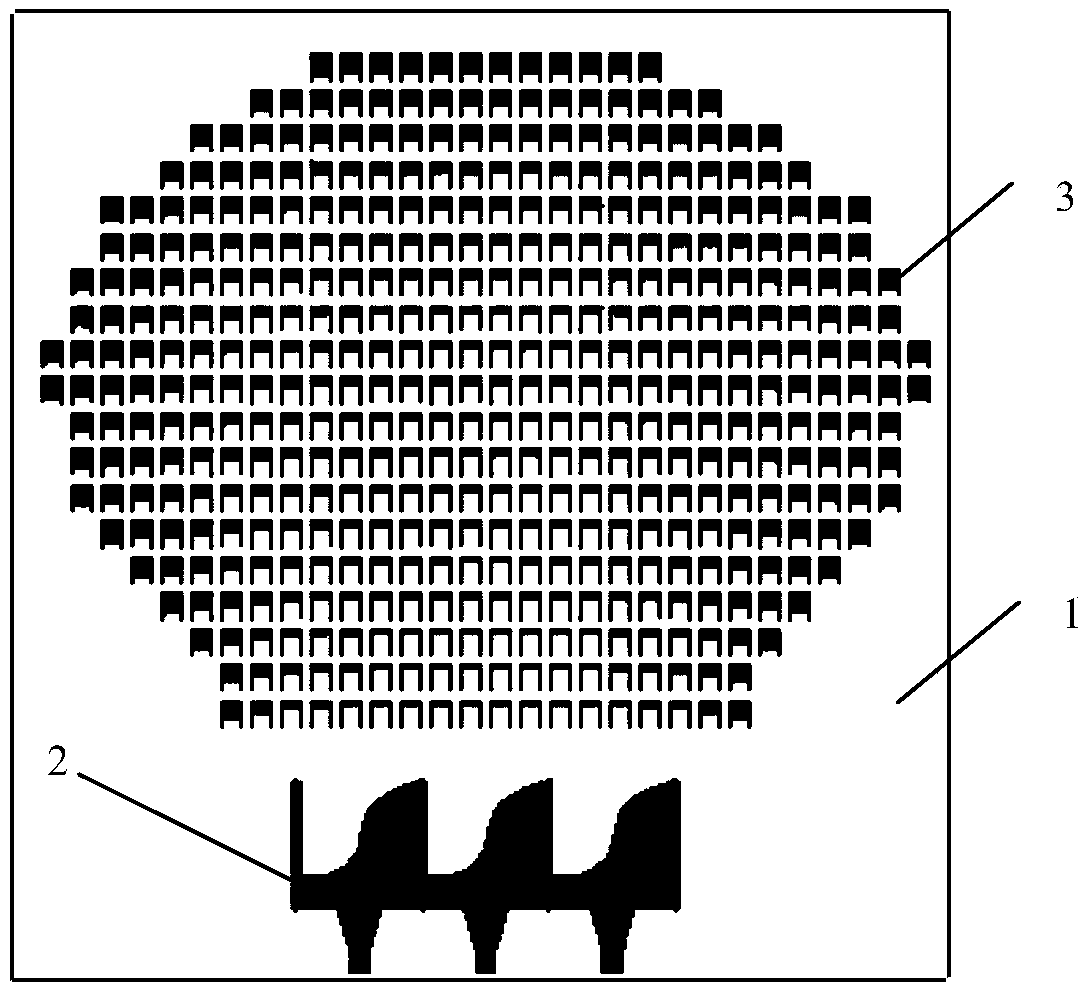
[0021] combine Figure 2 to Figure 11 The metasurface lens of the present invention is further described. Such as figure 2 As shown, the optical conversion-based metasurface lens of the present invention is mainly composed of a feed source 2 and a lens body 3 , and the lens body is integrated on a dielectric substrate 1 . The feed source 2 is composed of three positive and negative vivald antennas, and the main body of the lens is composed of discretely distributed metal U-shaped structural units. The distribution of the U-shaped structural unit is evolved from the distribution of the Lunberg lens through optical transformation. This distribution makes the arc-shaped focusing surface of the Lunberg lens flattened into a plane. Therefore, when the lens is excited by different positive and negative vivaldi antennas , the surface waves supported by the lens direct radiation in different directions.

[0022] The adjustment of the refractive index of the lens body is controlled...


PUM


Abstract

The invention discloses a super surface lens antenna based on optical transformation and a manufacturing method of the super surface lens antenna. A super surface lens based on the optical transformation comprises a dielectric substrate, a feed source and a lens body, wherein the feed source and the lens body are arranged on the dielectric substrate, and the refractive index distribution of the lens body is formed by carrying out optical transformation on the luneberg lens refractive index. The manufacturing method of the super surface lens based on the optical transformation comprises the step of transforming the refractive index distribution of the luneberg lens into the refractive index distribution of the lens body through optical transformation, and the step of integrating a U-type structure unit and the feed source on the dielectric substrate according to the refractive index distribution of the lens body. The lens has the effect of directed radiation of a traditional luneberg lens, meanwhile, the transformed lens has a leveled focusing surface, and better feed and integration are facilitated.

Description

technical field [0001] The invention relates to a surface plasmon lens based on a novel artificial electromagnetic material, which can be used in the fields of microwave, millimeter wave and terahertz. Background technique [0002] Such as figure 1 As shown, the existing Luneburg lens is placed in a rectangular area, wherein a part of the Luneburg lens is outside the rectangle, and the curved focusing surface of the Luneburg lens is not conducive to feeding and integration. On the other hand, the traditional spherical Lunberg lenses also have the problems of high loss and difficulty in fabrication. Contents of the invention [0003] Purpose of the invention: the present invention provides a metasurface lens antenna based on optical transformation and its manufacturing method, which introduces optical transformation into the control of surface waves; flattens the arc-shaped focal plane of the existing Lunberg lens for better feed and integration. [0004] Technical solut...

Claims


Application Information

Patent Timeline
IPC IPC(8): H01Q15/02H01Q19/06H01Q21/00
Inventor 崔铁军万向
Owner SOUTHEAST UNIV
Learn More