Optical fiber winding machine provided with wire pressing wheel

A technology with a wire crimping and wire take-up machine, which is applied in the direction of conveying filamentous materials, thin material processing, transportation and packaging, etc. It can solve problems such as fiber slack and damage, and achieve the effect of increasing the amount of wire taking-up and improving the effect

Inactive Publication Date: 2014-01-15
成都亨通光通信有限公司
View PDF5 Cites 3 Cited by
  • Summary
  • Abstract
  • Description
  • Claims
  • Application Information

AI Technical Summary

Problems solved by technology

[0003] The purpose of the present invention is to overcome the deficiencies of the current technology and provide an optical fiber take-up machine equipped with crimping wheels, which solves the shortcomings of the existing winding machines, such as loose optical fibers and easy damage

Method used


Image

  • Optical fiber winding machine provided with wire pressing wheel
  • Optical fiber winding machine provided with wire pressing wheel
  • Optical fiber winding machine provided with wire pressing wheel

Examples


Embodiment Construction

[0017] Below in conjunction with embodiment the present invention is described in further detail, but structure of the present invention is not limited to following embodiment:

[0018] 【Example】

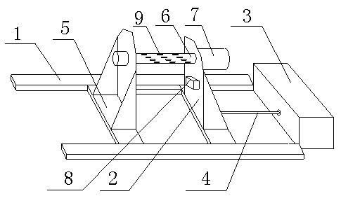
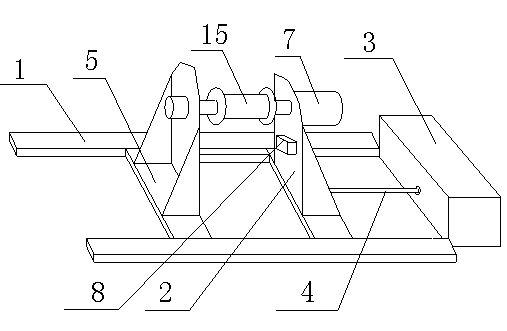
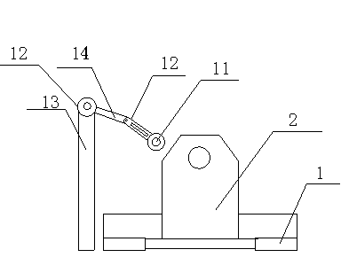
[0019] Such as figure 1 , figure 2 , image 3 As shown, the optical fiber take-up machine provided with crimping wheels includes a track 1, a trolley 2, a traction device 3 and a crimping device 10, the trolley 2 is slidably arranged on the track 1, and is passed through a stretching rod 4 Connect the traction device 3, the pulley 2 includes a base 5 and a rotating shaft 6 installed on the base 5, the rotating shaft 6 is driven to rotate by a rotating motor 7 installed on the base 5, the crimping device 10 includes a crimping roller 11, a crimping Arm 12 and pillar 13, described crimping arm 12 is rotatably installed on the pillar 13, and crimping roller 11 is installed on crimping arm 12 ends.

[0020] Further, the crimping arm 12 includes two sections of straight arms 14 that...


PUM


Abstract

The invention discloses an optical fiber winding machine provided with a wire pressing wheel. The optical fiber winding machine comprises a rail (1), a tackle (2) and a traction device (3). The tackle (2) is arranged on the rail (1) in a sliding mode and connected with the traction device (3) through a stretching rod (4). The tackle (2) comprises a base (5) and a rotary shaft (6) installed on the base (5), and the rotary shaft (6) is driven to rotate through a rotating motor (7) installed on the base (5). The optical fiber winding machine has the advantages that a winding drum is driven by the motor to perform winding, only one traction device is adopted, the thickness of an optical fiber is sensed through a sensor, the transverse motion speed of the winding drum requiring traction is calculated so that the optical fiber can be evenly wound on the winding drum, thus, not only is a large amount of manpower saved, but also the optical fiber is distributed evenly and will not knot when being unwound, and the optical fiber is protected.

Description

technical field [0001] The invention relates to an optical fiber take-up machine provided with a crimping wheel. Background technique [0002] The take-up is the last link in the production of optical fiber. It is the device that collects the optical fiber on the take-up barrel. Generally, it pays attention to the evenness of the take-up to facilitate the use of the later pay-off. However, the optical fiber on the existing take-up machine is not fit The ground is wound on the take-up barrel, so the optical fiber on the barrel is very loose, so the effect of winding is not very good, and the optical fiber is still easy to be crushed. Contents of the invention [0003] The purpose of the present invention is to overcome the deficiencies of the current technology and provide an optical fiber take-up machine equipped with a crimping wheel, which solves the shortcomings of the existing take-up machine that the optical fiber wound on the winding machine is loose and easy to caus...

Claims


Application Information

Patent Timeline
Patent Type & Authority Applications(China)
IPC IPC(8): B65H54/04B65H54/28B65H54/46B65H54/52
Inventor 孙义兴何吉焱许建国陈曲刘东陈治均
Owner 成都亨通光通信有限公司
Why Eureka
Try Eureka