
An anti-reflux biliary stent

A kind of bile duct, stent body technology

Active Publication Date: 2015-10-07
SECOND MILITARY MEDICAL UNIV OF THE PEOPLES LIBERATION ARMY
View PDF6 Cites 0 Cited by
  • Summary
  • Abstract
  • Description
  • Claims
  • Application Information

AI Technical Summary

Problems solved by technology

[0003] At present, the existing anti-reflux biliary plastic stent has a very long windsock-like anti-reflux structure attached to the end of the stent. This kind of stent has been proved by foreign scholars to have a certain anti-reflux effect, but in practice There are difficulties in stent release during operation, so it has not been able to be applied clinically
[0004] Chinese patent document CN200810036949.1, application date 2008.05.04 discloses a screw-lock type biliary stent, Chinese patent document CN201010116503.7, application date 2010.02.12 discloses a recyclable biliary stent, but currently there is no Biliary tract reflux, simple structure, easy to use, suitable for clinical application of biliary plastic stent has not been reported

Method used


Image

  • An anti-reflux biliary stent
  • An anti-reflux biliary stent
  • An anti-reflux biliary stent

Examples


Embodiment 1

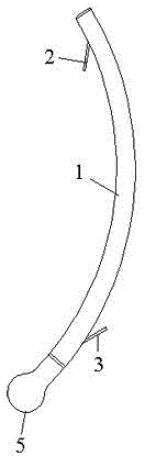
[0029] Please refer to figure 1 , figure 1 It is a structural schematic diagram of the anti-reflux biliary stent of the present invention. The biliary stent is provided with a stent body 1, and the stent body 1 is a tubular structure. The head of the stent body 1 is provided with a head end wing 2, and the tail is provided with a tail end wing 3. Both the head side wings 2 and the tail side wings 3 are hung upside down on the support body 1 in a hook shape. The tail end of the support body 1 is also provided with a groove 4 (not shown in the figure), and the groove 4 surrounds the support body 1 in a circle, that is, it is ring-shaped. An anti-reflux valve 5 is installed in the groove 4, and the anti-reflux valve 5 is in the shape of a pacifier.

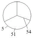
[0030] Please refer to figure 2 , figure 2 It is a disassembly diagram of the anti-reflux biliary stent anti-reflux valve and the stent body of the present invention. The cross section of the groove 4 is arc-shaped, and the c...

Embodiment 2

[0033] The anti-reflux biliary stent of this embodiment is the same as that of the embodiment, except that the shape of the release slit 54 is different. Please refer to Figure 4 , Figure 4 is another embodiment of an anti-reflux valve pocket. The release slit 54 is in the shape of a "ten".

[0034] Regarding the embodiment 1-2, it should be explained that: on the basis of the original biliary tract stent, the present invention adds a groove 4 to the tail end of the stent body 1, configures an anti-reflux valve 5, and integrates with the anti-reflux valve 5 The fixing ring 53 is tightly combined; the release slit 54 on the pouch 51 can ensure that bile is temporarily stored in the pouch 51 when it flows out in the forward direction, so that the pressure in the biliary tract is always greater than the pressure in the intestinal cavity; the spherical design makes the pouch 51 will not easily turn to the side of the bile duct due to the increase in the intraluminal pressure;...


PUM


Abstract

The invention relates to an anti-reflux biliary stent, which is provided with a stent body and side wings. The biliary stent is also provided with an anti-reflux valve; tube and a bag with a release slit, the fixing ring cooperates with the annular groove at the tail end of the stent body so that the anti-reflux valve is fixed on the stent body; the cross section of the groove is arc-shaped, and its central angle 180-240 degrees; the release gap is "Y" or "ten". The biliary tract stent of the present invention is equipped with an anti-reflux valve, and the anti-reflux valve is provided with a spherical pouch with a release slit, which can reduce the occurrence of biliary enteric reflux and biliary tract infection, and may prolong the patency of the plastic biliary stent. In the long term, the quality of life of patients is greatly improved, and the anti-reflux valve is firmly combined with the stent body, and it is not easy to loosen. The whole biliary stent has a simple structure and is easy to use, which is suitable for clinical promotion.

Description

technical field [0001] The invention relates to the technical field of medical devices, in particular to an anti-reflux biliary stent. Background technique [0002] With the promotion of clinical application of endoscopic technology, more and more patients with unresectable biliary and pancreatic diseases choose endoscopic treatment as a palliative treatment option. Biliary tract plastic stenting is chosen by most patients and their families because of its low cost. However, recurrent biliary tract infection and short patency of plastic stents after stenting often trouble us. Studies have reported that the existence of biliary enteric reflux is one of the important reasons leading to the occurrence of the above phenomenon. [0003] At present, the existing anti-reflux biliary plastic stent has a very long windsock-like anti-reflux structure attached to the end of the stent. This kind of stent has been proved by foreign scholars to have a certain anti-reflux effect, but in p...

Claims


Application Information

Patent Timeline
Patent Type & Authority Patents(China)
IPC IPC(8): A61F2/82
Inventor 王田田
Owner SECOND MILITARY MEDICAL UNIV OF THE PEOPLES LIBERATION ARMY
Learn More