PWM power amplifier for antenna

A technology for power amplifiers and antennas, applied to amplifiers, amplifiers with semiconductor devices/discharge tubes, electrical components, etc., can solve the problems of poor anti-interference performance and low reliability, and achieve strong anti-interference ability and high reliability , the effect of stabilizing the amplification factor

Active Publication Date: 2014-01-08
LUOYANG NORMAL UNIV
View PDF6 Cites 2 Cited by
  • Summary
  • Abstract
  • Description
  • Claims
  • Application Information

AI Technical Summary

Problems solved by technology

For example: an H-bridge motor controller (201010524194) that supports unipolar and bipolar pulse width modulation control, which is mainly implemented in software. The disadvantage is that the software method has low reliability and poor anti-interference performance

Method used


Image

  • PWM power amplifier for antenna
  • PWM power amplifier for antenna
  • PWM power amplifier for antenna

Examples


Embodiment Construction

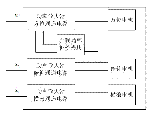
[0029] Such as figure 1 As shown in , the parallel power compensation module of the azimuth motor is spatially independent from the power amplifier body, and the two are electrically connected through a connector. In this way, under the condition that the power of the selected switching device remains unchanged, the driving power of the azimuth motor is doubled, which is beneficial to reducing the area of ​​the heat sink of the power amplifier and correspondingly reducing the weight and volume of the power amplifier. Similarly, if necessary, a parallel power compensation module can also be added to the pitch motor and roll motor.

[0030] The circuit principles of the azimuth 1, pitch 2 and roll 3 channels are exactly the same.

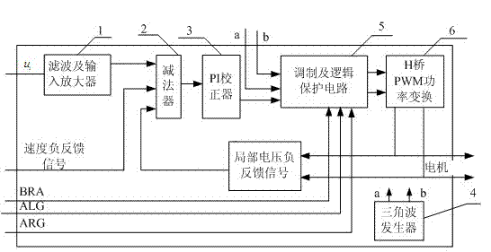
[0031] Such as figure 2 As shown, the output of filter and input amplifier 1 is connected to the input of subtractor 2, meanwhile, the speed negative feedback signal and local voltage negative feedback signal are respectively connected to the input...


PUM


Abstract

The invention discloses a PWM power amplifier for an antenna. By the adoption of the PWM power amplifier for the antenna, a rotation control signal is converted into the amplified electric power, so that a motor is driven to rotate. The PWM mode is applied to the power amplifier, a voltage, speed and position three-closed-loop control system is applied to an antenna servo system. A power compensation module is used as a parallel compensation output port of an azimuth shaft of the power amplifier so that the driving ability of the azimuth shaft can be improved. One power amplifier is provided with three independent power amplification channels, namely an azimuth channel, a pitching channel and a transverse-rolling channel, and PWM power amplification output is respectively conducted on control signals. Finally, the control signals are output to three direct-current servo motors comprising the azimuth direct-current servo motor, the pitching direct-current servo motor and the transverse-rolling direct-current servo motor. In this way, one power amplifier can fully meet the requirement for three-direction servo control over the radar antenna, and therefore the design of the antenna control system is simplified.

Description

technical field [0001] The invention relates to the field of amplifiers, in particular to a PWM power amplifier applicable to various types of radar antennas, satellite communication antennas, satellite antennas in motion and the like. technical background [0002] At present, for high-power motor speed control systems, it is mainly realized by increasing the power of a single power tube, but high-power switching tubes, especially domestic high-power switching tubes, due to complex manufacturing processes, difficult manufacturing, poor reliability, and high cost , Therefore, the application of domestic high-power switching devices has been limited. In addition, the existing PWM power amplifier is mainly in the form of microcontroller software, and the phenomenon of program crash may occur. [0003] The working mode of the H-bridge reversible PWM conversion circuit used in the existing amplifier: the current pulsation of the bipolar mode is large, and there is a phenomenon...

Claims


Application Information

Patent Timeline
Patent Type & Authority Applications(China)
IPC IPC(8): H03F3/217
Inventor 周涛张丽陈军王希娟张莉莉李玲
Owner LUOYANG NORMAL UNIV
Why Eureka
Try Eureka