
Roller cone disc type continuously variable transmission

A continuously variable transmission, cone-disc technology, applied in belts/chains/gears, friction transmission devices, elements with teeth, etc., can solve problems such as reducing geometric slip rate, accelerating traction surface wear, and small transmission power

Inactive Publication Date: 2014-01-08
佛山市顺德华兴船厂
View PDF6 Cites 14 Cited by
  • Summary
  • Abstract
  • Description
  • Claims
  • Application Information

AI Technical Summary

Problems solved by technology

[0003] The belt-driven continuously variable transmission mainly relies on variable-diameter driving and driven gears and metal belts to achieve stepless change in speed ratio. Obtain the best match between the transmission system and the engine operating conditions, and improve the fuel economy of the vehicle; in the last ten years, CVT (Continuously Variable Trans-mission) technology has made great progress and has been widely used In the field of low-power vehicles, however, it is limited by the material and technology of the metal strip, making the manufacturing cost very high
[0004]The bevel wheel type continuously variable transmission is mainly driven by the contact friction and lubricating oil film traction of the main and driven rigid elements (or through the intermediate element), and can be changed by changing its The working radius of the contact point is continuously variable. It has the advantages of stable transmission, low noise, simple structure, overload protection effect, and various forms. At present, there are more cone-disk ring-disk types, multi-disk types, and steel ball-cone types. Wheel type, diamond cone type, planetary cone disc type and planetary ring cone type continuously variable transmission, etc.; in the cone wheel friction type continuously variable transmission, when the cone wheel and the contacted transmission elements are under load and friction work, due to the cone wheel and the contacted transmission element Due to the geometric shape of the contacting transmission elements, the speed distribution in the contact area of ​​the two rolling elements is different, resulting in geometric slippage between the two rolling elements. The geometric slippage in the mechanism will increase the temperature of the traction oil and reduce the traction coefficient, resulting in transmission transmission of the transmission. Power and efficiency decline, etc., and at the same time, it will accelerate the wear of the traction surface and reduce the life of the transmission
[0005]In the prior art, in order to reduce the spin phenomenon in the contact area of ​​the friction transmission in the bevel wheel type continuously variable transmission, many designers will try their best according to the size of the transmission power Reduce the contact area between the bevel wheel and the contacted transmission element to reduce the geometric slip rate; however, to minimize the geometric slip rate in the bevel friction continuously variable transmission, only when the bevel wheel and the contacted When the contact area between the transmission elements is point contact, theoretically no geometric slip will occur, and the transmission efficiency at this time is also the highest; however, the smaller the contact area between the bevel wheel and the contacted transmission element, the lower the load-carrying capacity. The worse the transmission power is, the smaller the transmission power is; there is a contradiction between the above two
[0006]In recent years, a long taper-roller type continuously variable transmission has received extensive attention and research in the field of transmission, and there have been great innovations and breakthroughs in structure. The shape of the roller is such that the first conical surface on the intermediate roller is in the same direction as the conical surface of the active long bevel wheel and is in contact with the drive, and the second conical surface on the intermediate roller is also in the same direction as the conical surface of the driven long bevel wheel. , and contact the transmission, the continuously variable transmission significantly reduces the geometric slip rate generated by the transmission, and improves the transmission efficiency and power; however, the intermediate roller in the continuously variable transmission is parallel to the conical When the surface is adjusted to change speed, a large axial resistance or axial thrust will be generated, resulting in a reduction in mechanical efficiency and life
How to solve the above, there is no ideal solution in this field at present

Method used

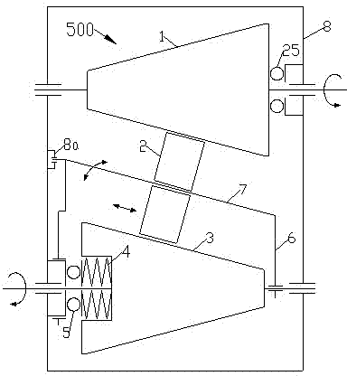
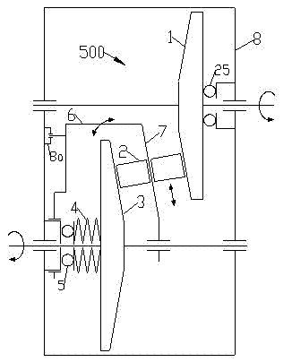
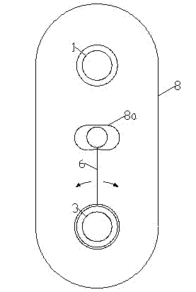

Image

  • Roller cone disc type continuously variable transmission
  • Roller cone disc type continuously variable transmission
  • Roller cone disc type continuously variable transmission

Examples


Embodiment Construction

[0130] The present invention will be described in further detail below according to accompanying drawing and embodiment:

[0131] Such as figure 1 , figure 2 , image 3 As shown, the roller-cone-disc continuously variable transmission of the present invention includes a bevel wheel support 8, at least one transmission wheel set 500 and at least one pressurizing device 4, and the transmission wheel set 500 includes a driving bevel wheel 3, at least one driven bevel wheel 1 , the roller bracket 6, the roller 2 corresponding to the number of the driven cone wheel 1, the guide device 7 corresponding to the number of the roller 2; the taper directions of the driving cone wheel 3 and the driven cone wheel 1 are oppositely set, and the adjacent taper lines are kept Parallel, the driving cone wheel 3 and the driven cone wheel 1 are rotationally connected with the cone wheel bracket 8 respectively; the pressurizing device 4 is set at the large diameter end of the taper of the drivin...


PUM


Abstract

The invention discloses a roller cone disc type continuously variable transmission. A driving cone pulley and a driven cone pulley are connected with a cone pulley support in a rotating mode. A pressure device pushes the driving cone pulley to apply pressure in the axial direction. A roller makes contact with the circular conical surface of the driving cone pulley and the circular conical surface of the driven cone pulley for transmission, and is arranged on a roller support in a sliding mode parallel to the conicity line of the driving cone pulley. The roller support and the driving cone pulley are arranged on the cone pulley support in a reciprocating rotating mode within a certain angle range around the same axis. The swing angle of the roller support on the cone pulley support is controlled to change the positions of two transmission mass points on the roller so that the roller can move automatically in the axial direction; moreover, the transmission ratio of the driving cone pulley to the driven cone pulley is changed continuously to realize stepless speed change. The roller cone disc type continuously variable transmission can be applied to various fields such as vehicles, ships and mechanical transmission.

Description

technical field [0001] The invention relates to the field of mechanical continuously variable transmissions, in particular to a roller-cone-disk type continuously variable transmission. Background technique [0002] The mechanical continuously variable transmission has many advantages such as simple structure, high reliability, and convenient stepless speed regulation. At present, there are many types of cone wheel, planetary cone wheel, belt, chain, and pulsation. [0003] The belt-driven continuously variable transmission mainly relies on variable-diameter driving and driven gears and metal belts to achieve stepless change in speed ratio. Obtain the best match between the transmission system and the engine operating conditions, and improve the fuel economy of the vehicle; in the last ten years, CVT (Continuously Variable Trans-mission) technology has made great progress and has been widely used In the field of low-power vehicles, however, it is limited by the material and...

Claims


Application Information

Patent Timeline
IPC IPC(8): F16H15/02
CPCF16H15/40F16H15/503F16H61/26F16H61/66F16H2061/6604
Inventor 郭克亚
Owner 佛山市顺德华兴船厂
Learn More