
Ceramic substrate dual surface photolithography technique and structure

A ceramic substrate, double-sided lithography technology, applied in the field of lithography process, can solve the problems of product quality impact, high production cost, position deviation, etc., and achieve the effects of reducing production cost, improving production efficiency, and improving pass rate

Inactive Publication Date: 2014-01-01
刘毅楠
View PDF0 Cites 5 Cited by
  • Summary
  • Abstract
  • Description
  • Claims
  • Application Information

AI Technical Summary

Problems solved by technology

At present, the commonly used method is to first carry out metallization wiring on the upper surface of the ceramic substrate, and then reverse the ceramic substrate, and carry out metal wiring on the lower surface of the ceramic substrate. In the process of inversion, position deviation is easy to occur, which will cause deviation of the metal pattern on the upper and lower surfaces of the ceramic substrate, which will affect the quality of many products, often produce a large number of defective products, and the product qualification rate is low. The production cost of the enterprise is higher

Method used


Image

  • Ceramic substrate dual surface photolithography technique and structure

Examples


Embodiment Construction

[0023] Preferred embodiments of the present invention will be described in detail below in conjunction with the accompanying drawings.

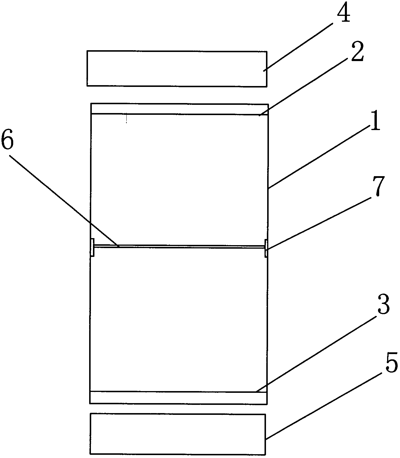
[0024] Such as figure 1 As shown, the double-sided lithography structure includes a support frame 1, an upper mask 2 is provided at the upper end of the support frame 1, and a lower mask 3 is provided at the lower end of the support frame 1, and the upper mask 2 and the lower mask 3 are respectively according to The metal graphics on the upper and lower surfaces of the ceramic substrate are required to be made. An exposure device 4 is provided above the upper mask 2 , and an exposure device 5 is provided below the lower mask 3 . A ceramic substrate support frame 7 is also provided between the upper mask plate 2 and the lower mask plate 3. The ceramic substrate support frame 7 is generally located in the middle of the support frame 1, and the ceramic substrate support frame 7 is provided with a ceramic substrate 6. , the center positions of ...


PUM


Abstract

The invention discloses a ceramic substrate dual surface photolithography structure. The dual surface photolithography structure comprises a supporting frame, an upper mask plate is arranged at the upper end of the supporting frame, a lower mask plate is arranged at the lower end of the supporting frame, two exposure devices are arranged above the upper mask plate and below the lower mask plate respectively, a ceramic substrate supporting rack is arranged between the upper mask plate and the lower mask plate, a ceramic substrate is arranged on the ceramic substrate supporting rack, and the center positions of the upper mask plate, the ceramic substrate and the lower mask plate correspond vertically. According to the ceramic substrate dual surface photolithography structure, the exposure devices are simultaneously arranged above the upper mask plate and below the lower mask plate respectively, and the upper surface and the lower surface of the ceramic substrate are exposed simultaneously through the upper exposure device and the lower exposure device, so that absolute inosculation of metal graph positions on the upper surface and the lower surface of the ceramic substrate is ensured, offset can not happen, therefore, the quality of the ceramic substrate is ensured, the yield of the product is improved, production efficiency can be effectively improved, and production cost of an enterprise can be reduced by the adoption of the mode.

Description

technical field [0001] The invention relates to a photolithography process, in particular to a method for performing photolithography on the upper and lower sides of a ceramic substrate and a photolithography structure for realizing the method. Background technique [0002] The development of modern microelectronics technology is extremely rapid, especially various optoelectronic devices are gradually developing in the direction of miniaturization, large-scale integration, high efficiency, and high reliability. However, with the improvement of electronic system integration, its power density increases, the heat generated by electronic components and the overall work of the system rises, and the increase in system operating temperature will cause semiconductor device performance deterioration, device damage, delamination, etc., and even make packaging Chips burn out, so effective electronic packaging must address the heat dissipation of electronic systems. [0003] The subst...

Claims


Application Information

Patent Timeline
Patent Type & Authority Applications(China)
IPC IPC(8): H01L21/48G03F7/00
CPCH01L21/4807H01L21/0274H01L21/4846
Inventor 刘毅楠
Owner 刘毅楠
Learn More