
WLAN indoor location fingerprint positioning method used for real-time monitoring

An indoor location and real-time monitoring technology, applied in advanced technology, electrical components, network topology, etc., can solve the problems of high energy consumption of positioning server energy system, large data consumption of mobile terminal transmission, and large search range of physical space. Achieve the effect of reducing overall energy consumption, prolonging the working time and prolonging the service life

Active Publication Date: 2013-12-25
严格集团股份有限公司
View PDF5 Cites 57 Cited by
  • Summary
  • Abstract
  • Description
  • Claims
  • Application Information

AI Technical Summary

Problems solved by technology

[0004] The present invention aims to solve the problem that in the position fingerprint positioning system, the dimension of the signal data used for positioning is too high, resulting in excessive consumption of data transmitted by the mobile terminal, and the excessively large search range of the physical space and the high dimension of the signal space make the positioning algorithm complex If it is too large, it will cause the problem of excessive energy consumption of the positioning server and the total energy consumption of the system, thus providing a WLAN indoor location fingerprint positioning method for real-time monitoring

Method used


Image

  • WLAN indoor location fingerprint positioning method used for real-time monitoring
  • WLAN indoor location fingerprint positioning method used for real-time monitoring
  • WLAN indoor location fingerprint positioning method used for real-time monitoring

Examples


specific Embodiment approach 1

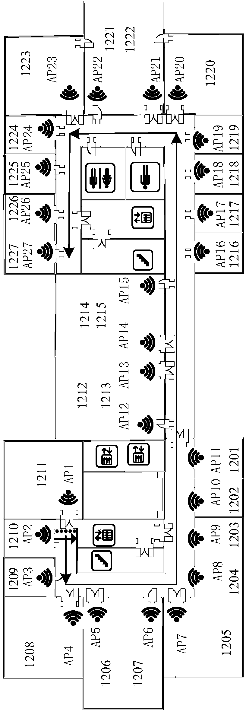
[0015] Specific implementation mode one: refer to figure 1 Describe this embodiment in detail, a WLAN indoor position fingerprint positioning method for real-time monitoring described in this embodiment, the indoor positioning space is provided with N reference nodes equally spaced in the indoor positioning space and M Wireless access node AP, so that any position in the indoor positioning space can receive the wireless signal sent by at least one wireless access node AP, and the received signal strength should be greater than -95dBm, M and N are both positive integers;

[0016] According to the physical locations of all reference nodes, the K-means clustering algorithm is used to divide the indoor positioning space where the reference nodes are located into α-block positioning sub-regions, denoted as: S 1 ,S 2 ,...,S α , where α is a positive integer, and the positioning method includes the following steps:

[0017] Step 1: The mobile terminal to be positioned uses the wei...

specific Embodiment approach 2

[0021] Specific embodiment two: this embodiment is to further explain a kind of WLAN indoor position fingerprint location method for real-time monitoring described in specific embodiment one, in this embodiment, the described K-means clustering algorithm will refer to A method for dividing the indoor positioning space where the nodes are located into α-block positioning sub-regions, which includes the following steps:

[0022] Step 1: Randomly select a point in the indoor positioning space as the origin to establish a Cartesian coordinate system, use the physical positions of N reference nodes as parameters to describe the reference nodes, randomly select K initial cluster centers among the N reference nodes, and record For: Z 1 (1), Z 2 (1),...,Z K (1), where K=α and 0≤K<N, the number in the brackets of the clustering center indicates the number of iterations, and then perform step 1 and 2;

[0023] Step 12: Assign the remaining reference nodes to an initial cluster center...

specific Embodiment approach 3

[0033] Specific implementation mode three: refer to figure 2Describe this embodiment in detail. This embodiment is a further description of a WLAN indoor location fingerprint positioning method for real-time monitoring described in Embodiment 1. In this embodiment, the weight matrix and step 1 described in Step 1 B. The transformation matrix is ​​obtained by the following steps:

[0034] Step 2 1: Establish the fingerprint data space Radio Map data according to the distribution of the indoor positioning space and its internal reference nodes and wireless access nodes AP, and then perform step 2 2;

[0035] Step 2 2: Using the fingerprint data space Radio Map data obtained in Step 2 1, in each positioning sub-area and each pair of adjacent positioning sub-areas, use the received signal strength value RSS value of all wireless access nodes AP As a parameter, M wireless access nodes AP are clustered and divided, and then step 2 and 3 are performed;

[0036] Step 23: Take the M...


PUM


Abstract

The invention discloses a WLAN indoor location fingerprint positioning method used for real-time monitoring and belongs to the technical field of WLAN indoor positioning. The WLAN indoor location fingerprint positioning method used for real-time monitoring solves the problem that according to an existing location fingerprint positioning system, power consumption of a positioning server and the total power consumption of the system are excessive. According to the WLAN indoor location fingerprint positioning method used for real-time monitoring, the physical region of a reference point is divided into regions firstly, and then the real-time performance of positioning and monitoring is improved by 6 times; then AP signals received by the reference point are clustered and screened according to the regions, and then the real-time performance of positioning and monitoring is improved by another 3 times; finally data are transmitted in a compressed mode and then are reconstructed, power consumption of a mobile terminal is reduced to 33%, then working time is prolonged, and the overall power consumption of the positioning monitoring system is reduced to 33%. According to the WLAN indoor location fingerprint positioning method used for real-time monitoring, one positioning server is used for positioning and monitoring the mobile terminal, and the service cycle of the mobile terminal is prolonged by 3 times. The WLAN indoor location fingerprint positioning method used for real-time monitoring can be used in occasions where positioning and monitoring are needed frequently.

Description

technical field [0001] The invention relates to an indoor positioning method and belongs to the technical field of WLAN indoor positioning. Background technique [0002] Wireless Local Area Network (WLAN) technology, that is, Wireless Local Area Network, is the product of the combination of computer network and wireless communication technology, aiming to provide users with wireless broadband access services, so as to meet the needs of modern society for mobile office and mobile life. WLAN does not need wiring, the network cost is greatly reduced, and the mobility is strong. These advantages make the popularity of WLAN is changing with each passing day. Currently, WLANs are widely deployed by various organizations and individuals in different occasions all over the world, such as campuses, hospitals, airports, and parking lots. [0003] With the popularization and application of WLAN technology, the demand for positioning information in the indoor environment is also increa...

Claims


Application Information

Patent Timeline
IPC IPC(8): H04W64/00H04W84/12
CPCY02D30/70
Inventor 马琳郑秀明徐玉滨田硕孟维晓崔扬
Owner 严格集团股份有限公司
Learn More