Sputtering ion gun
An ion gun and ion technology, applied in the field of sputtering ion guns, can solve the problems of direction deviation, low ion movement speed, low ionization efficiency, etc., and achieve the effects of simple structure, improved surface treatment effect, and convenient use.
- Summary
- Abstract
- Description
- Claims
- Application Information
AI Technical Summary
Problems solved by technology
Method used
Image
Examples
Embodiment 1
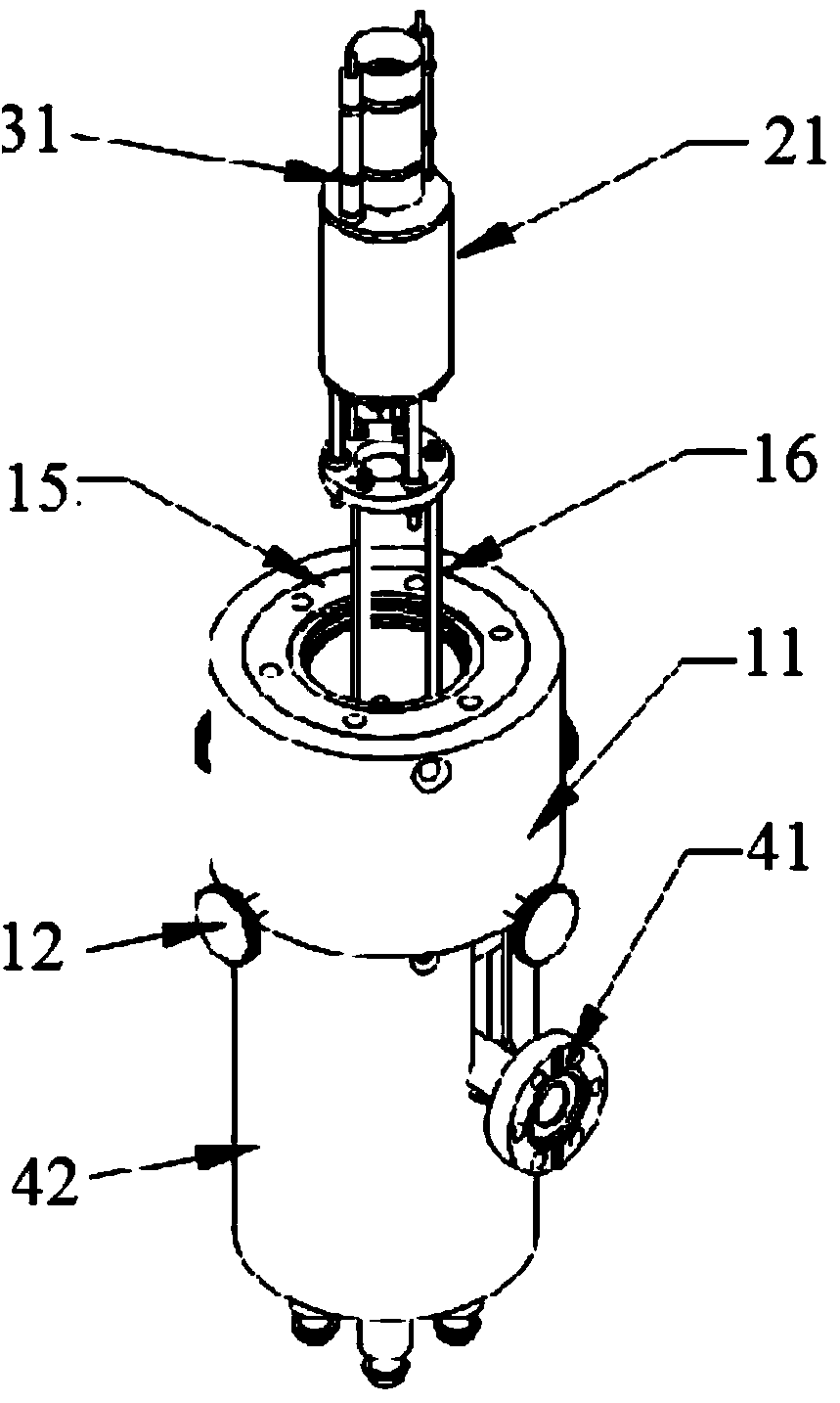
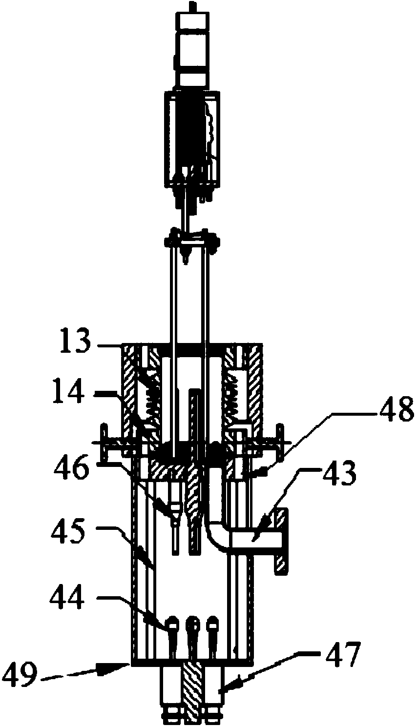
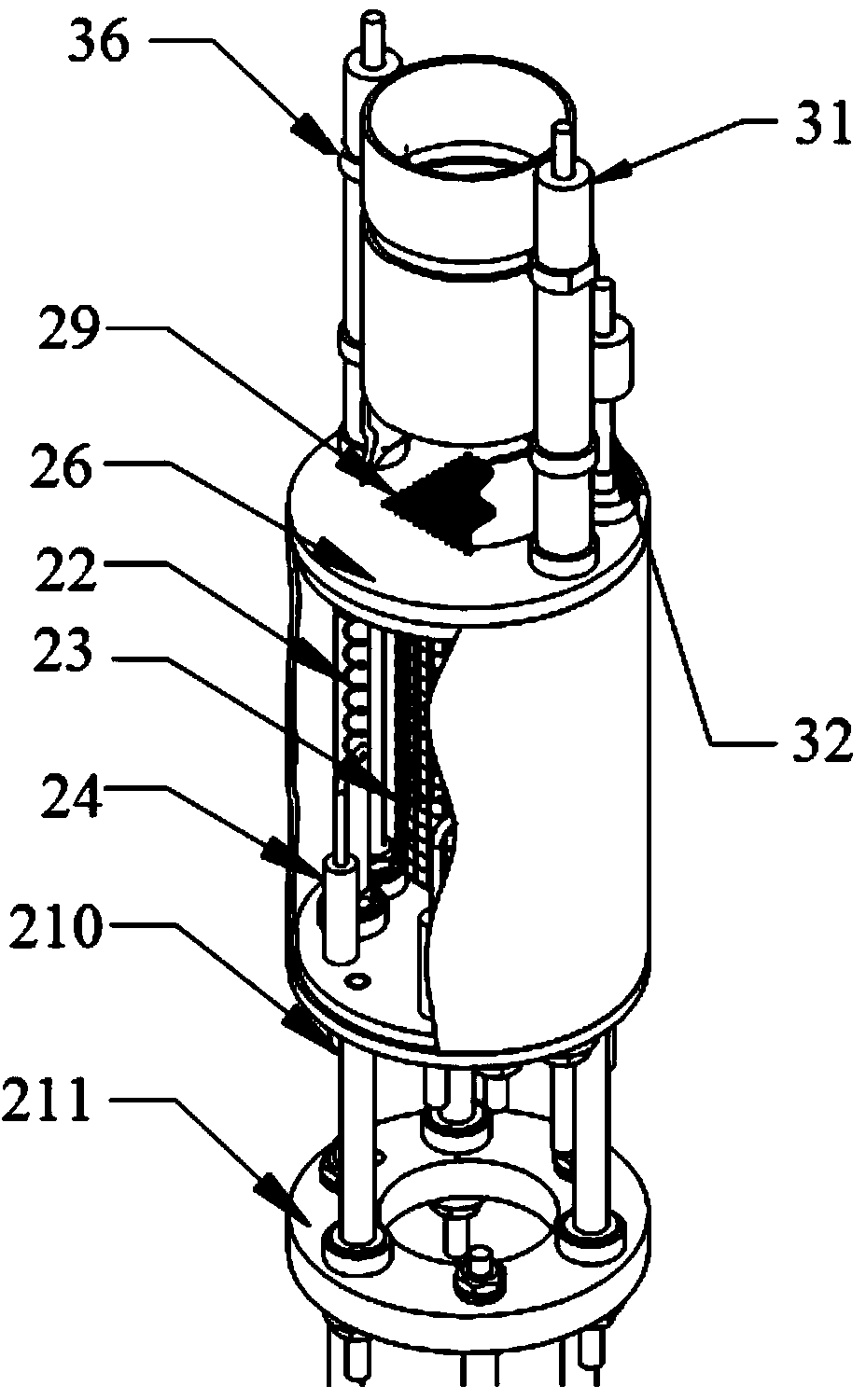
[0042] The bottom of a sputtering ion gun mainly includes a flange 41 , an argon gas introduction tube 43 , an electrode 44 , a BNC electrode support rod 45 , an electrode 46 , a BNC electrode 47 and an outer cover 42 . Wherein the argon gas inlet pipe 43 is connected with the CF16 flange 41 by welding. The inner diameter of the argon gas inlet pipe is 10 mm, and the CF16 flange 41 welded at the other end of the pipe is connected to the gas tank after passing through a gas flow fine-tuning valve. The five BNC electrodes at the bottom of the ion gun pass through the bottom end plate 49 leaving electrodes 44 inside the ion gun. In use, the electrodes 44 and 46 are correspondingly connected through cables. The electrode 46 has an electrode connector in the cavity of the airflow regulating device, and the electrode connector is connected to the electron acceleration grid electrode 28, the filament electrode 24, and the high-voltage electrode of the focusing lens 212 respectively ...
PUM
 Abstract
Description
Claims
Application Information
 - R&D
- Intellectual Property
- Life Sciences
- Materials
- Tech Scout
- Unparalleled Data Quality
- Higher Quality Content
- 60% Fewer Hallucinations
Browse by: Latest US Patents, China's latest patents, Technical Efficacy Thesaurus, Application Domain, Technology Topic, Popular Technical Reports.
© 2025 PatSnap. All rights reserved.Legal|Privacy policy|Modern Slavery Act Transparency Statement|Sitemap|About US| Contact US: help@patsnap.com


