Liquid gasification burner

A burner and liquid technology, applied in the direction of burner, combustion method, combustion type, etc., can solve the problems of unfavorable combustion exhaust gas emission, inconvenient processing and maintenance, complex internal structure, etc., and achieve good social and ecological benefits, processing and maintenance Convenient, compact and reasonable effect

Inactive Publication Date: 2013-12-25
苏志勇
View PDF11 Cites 9 Cited by
  • Summary
  • Abstract
  • Description
  • Claims
  • Application Information

AI Technical Summary

Problems solved by technology

Although the combustion furnace optimizes the structure of the vaporization chamber, due to the lack of air intake structure, there is insufficient oxygen during combustion, which is not conducive to the full combustion of fuel
[0004] Chinese patent CN2256072Y discloses a bio-combustion liquid stove, which is composed of a furnace shell, a pot frame, a general name for a vaporization chamber, a fire distribution plate, a copper head, an electronic ignition mechanism and a vapor-liquid pipe, but because the stove has no Air intake structure, lack of oxygen during combustion, long preheating time, and scattered fire; the exhaust pipe is located at the lower part of the stove, which is not conducive to the discharge of combustion exhaust gas, making the inside of the stove pressurized and unsafe; the inlet of the stove There are many liquid pipes, the internal structure is complicated, and it is inconvenient to process and maintain

Method used


Image

  • Liquid gasification burner
  • Liquid gasification burner
  • Liquid gasification burner

Examples


Embodiment 1

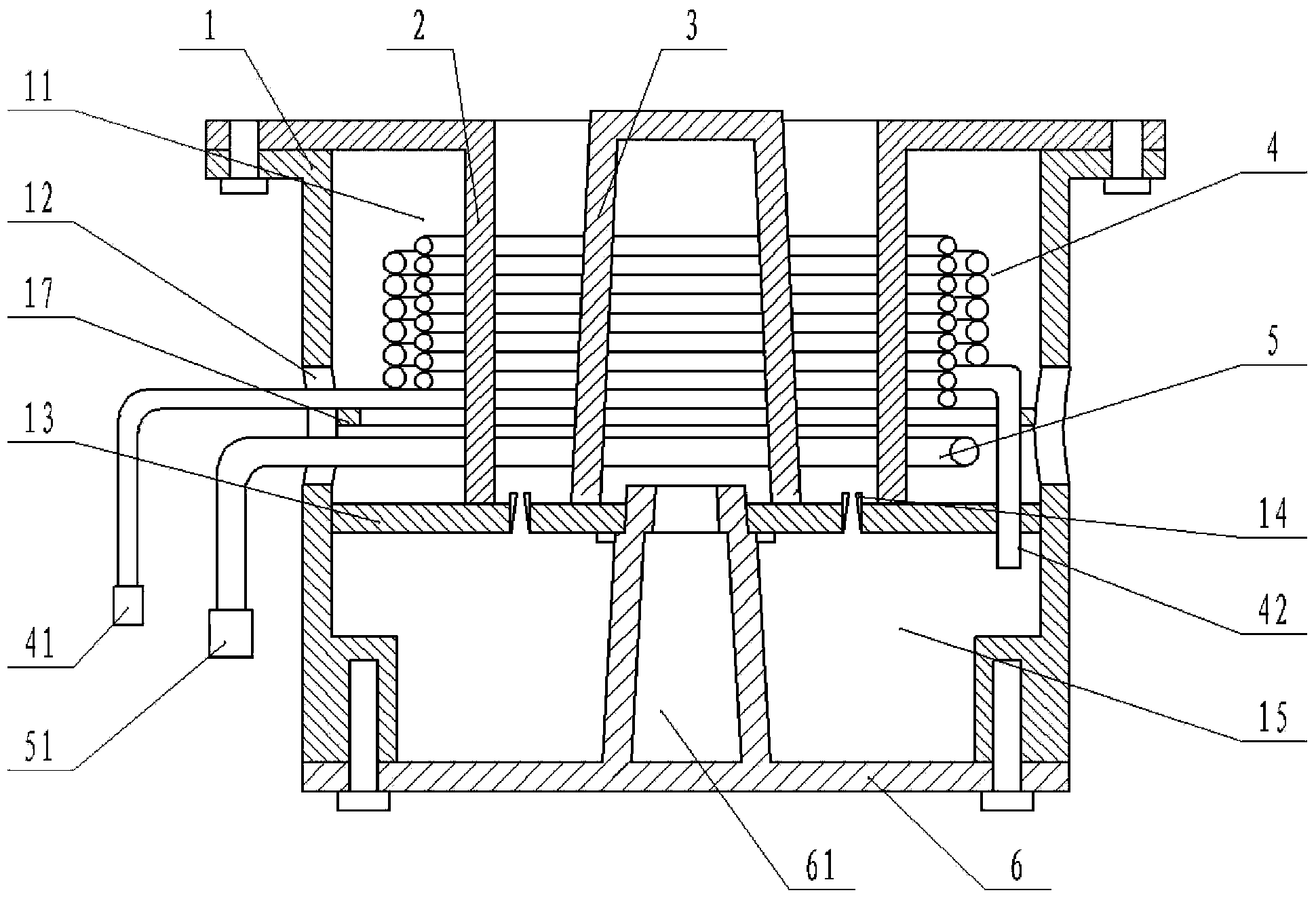
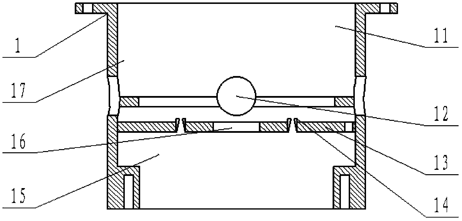
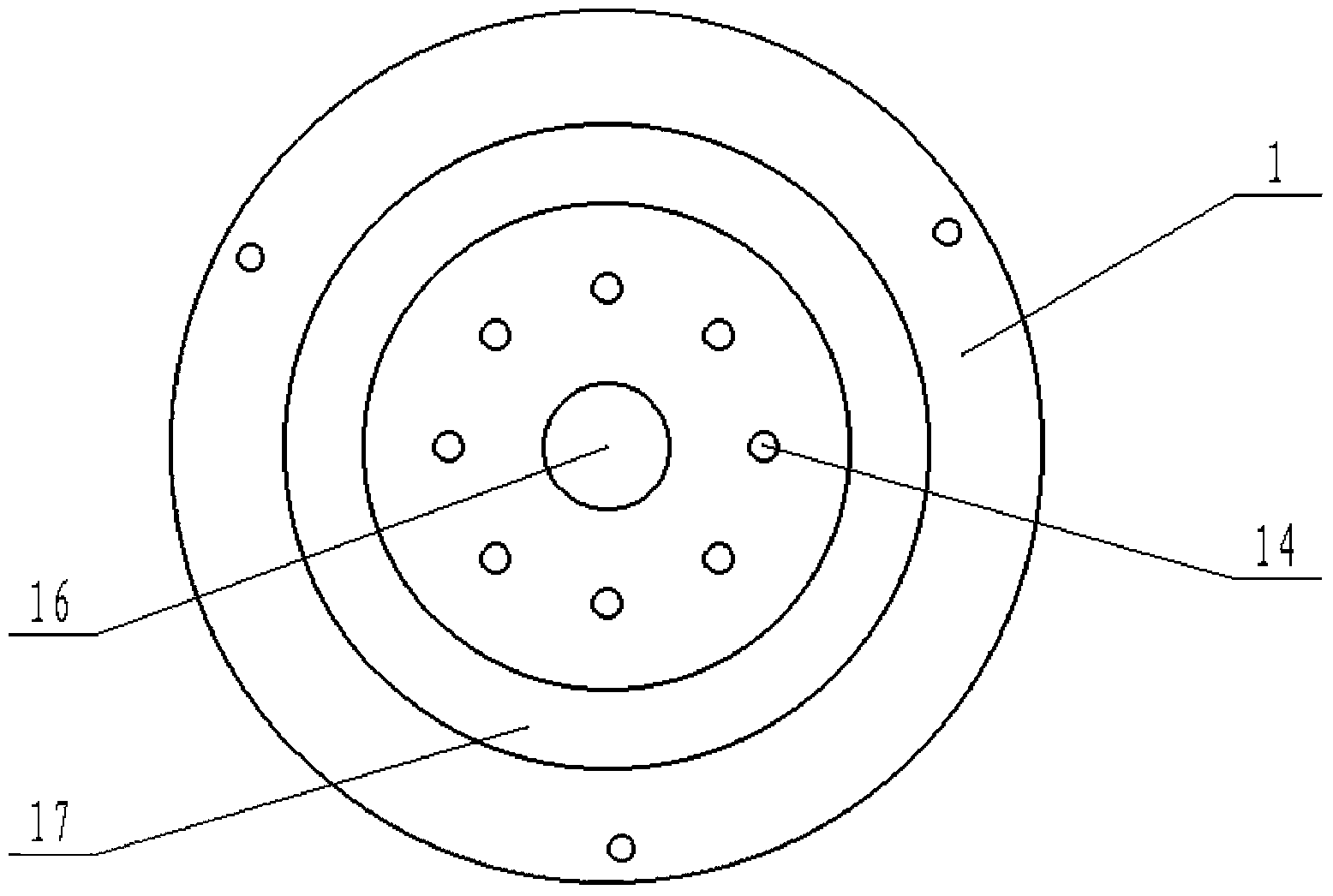
[0027] A liquid gasification burner, comprising a furnace body 1, an outer gas distribution cover 2, an inner gas distribution cover 3 and a base 6, the furnace body 1 is divided into upper and lower layers through a partition 13, the upper layer is a furnace 11, and the lower layer is a The gasification chamber 15 and the furnace 11 are provided with four air inlet holes 12 and a flange 17 for fixing the gasification coil 4 on the four walls of the furnace body 1 . The furnace 11 is provided with an outer gas distribution hood 2 , an inner gas distribution hood 3 , a preheating coil 5 and a gasification coil 4 . The outer gas distribution hood 2 is placed in the furnace 11, and the outer gas distribution hood 2 is fixedly connected to the upper end of the furnace body 1 with bolts; the inner gas distribution hood 3 is placed in the middle of the furnace 11. Small combustion-supporting holes 8 are evenly arranged on the four walls of the lower end of the outer layer gas distri...

Embodiment 2

[0032] A liquid gasification burner, comprising a furnace body 1, an outer gas distribution cover 2, an inner gas distribution cover 3 and a base 6, the furnace body 1 is divided into upper and lower layers through a partition 13, the upper layer is a furnace 11, and the lower layer is a The gasification chamber 15 and the furnace 11 are provided with 6 air inlet holes 12 and a flange 17 for fixing the gasification coil 4 on the four walls of the furnace body 1 . The furnace 11 is provided with an outer gas distribution hood 2 , an inner gas distribution hood 3 , a preheating coil 5 and a gasification coil 4 . The outer gas distribution hood 2 is placed in the furnace 11, and the outer gas distribution hood 2 is fixedly connected to the upper end of the furnace body 1 with bolts; the inner gas distribution hood 3 is placed in the middle of the furnace 11. Small combustion-supporting holes 8 are evenly arranged on the lower walls of the outer layer gas distribution hood 2 and t...

Embodiment 3

[0037] A liquid gasification burner, comprising a furnace body 1, an outer gas distribution cover 2, an inner gas distribution cover 3 and a base 6, the furnace body 1 is divided into upper and lower layers through a partition 13, the upper layer is a furnace 11, and the lower layer is a The gasification chamber 15 and the furnace 11 are provided with 8 air inlet holes 12 and a flange 17 for fixing the gasification coil 4 on the four walls of the furnace body 1 . The furnace 11 is provided with an outer gas distribution hood 2 , an inner gas distribution hood 3 , a preheating coil 5 and a gasification coil 4 . The outer gas distribution hood 2 is placed in the furnace 11, and the outer gas distribution hood 2 is fixedly connected to the upper end of the furnace body 1 with bolts; the inner gas distribution hood 3 is placed in the middle of the furnace 11. Small combustion-supporting holes 8 are evenly arranged on the four walls of the lower end of the outer layer gas distribut...


PUM


Abstract

The invention discloses a liquid gasification burner, which comprises a stove body, an outer gas distribution cover, an inner gas distribution cover and a base, the four walls of the stove body are provided with air inlets, and the stove body is divided into a stove chamber and a gasification chamber by a partition; the outer gas distribution cover and the inner gas distribution cover are arranged in the stove chamber, and the four walls of each of the outer gas distribution cover and the inner gas distribution cover are provided with burning-supporting holes; the base is connected with the gasification chamber through bolts, and the liquid gasification burner also comprises a preheating coil and a gasification coil. Fuel respectively enters the preheating coil and the gasification coil, the heat produced by the burning liquid fuel flowing out of the preheating coil can gasify the fuel in the preheating coil, the gasified fuel enters the gasification chamber via the gas outlet of the gasification coil, and the gas flows out of the gasification chamber via flame nozzles on the partition to enter the stove chamber and burns. The fuel can be sufficiently burnt, the thermal efficiency is high, moreover, fire is evenly distributed, the environment cannot be polluted, and the safety performance is good.

Description

technical field [0001] The invention belongs to the technical field of daily life and industrial combustion equipment, and relates to a liquid gasification burner. Background technique [0002] Due to the unreasonable structure of the existing organic liquid burner, the technology is backward, resulting in low thermal conductivity of the burner, insufficient flame temperature, yellow and sometimes blue flame, poor gasification, and low combustion efficiency; It is necessary to inflate and pressurize or use a liquid pump to supply liquid, which is very easy to form high pressure or liquid leakage, and it is easy to cause danger when burning and cause adverse consequences. [0003] Chinese patent CN2430630Y discloses an alcohol engine combustion furnace. The gasification chamber is provided with an interlayer with a small top and a wide bottom. The combustion fluid tank is pressurized, and the other channel is sent to the combustion head for combustion. The principle of conve...

Claims


Application Information

Patent Timeline
IPC IPC(8): F23D11/00F23D11/36F23D11/44
Inventor 苏志勇苏日强
Owner 苏志勇
Why Eureka
Try Eureka