
Organic electroluminescent element, method for manufacturing organic electroluminescent element, and coating liquid for electron injection/transport layer

An electroluminescent element and electron injection technology, which is applied in the manufacture of electroluminescent light sources, electrical components, semiconductor/solid-state devices, etc., can solve problems such as poor production efficiency, shortened lifespan, and difficulty in uniformly controlling film thickness. Achieve high luminous efficiency and improve lifespan

Inactive Publication Date: 2013-12-18
DAI NIPPON PRINTING CO LTD
View PDF13 Cites 5 Cited by
  • Summary
  • Abstract
  • Description
  • Claims
  • Application Information

AI Technical Summary

Problems solved by technology

However, there are also the following problems: it is difficult to uniformly control the film thickness in a large area, the formation of a large-area organic layer takes a long time, so the production efficiency is poor, and a large-scale vacuum device is required, so the manufacturing cost is high.
In addition, for example, in the case of co-depositing the main component of the organic compound and the dopant of the metal or the metal compound to form an organic layer, since the vapor deposition temperature of the metal or the metal compound is higher than the vapor deposition temperature of the organic compound, Therefore, organic compounds decompose during vapor deposition, or their decomposed products are mixed into the film, so the life may be shortened

Method used


Image

  • Organic electroluminescent element, method for manufacturing organic electroluminescent element, and coating liquid for electron injection/transport layer
  • Organic electroluminescent element, method for manufacturing organic electroluminescent element, and coating liquid for electron injection/transport layer
  • Organic electroluminescent element, method for manufacturing organic electroluminescent element, and coating liquid for electron injection/transport layer

Examples


Embodiment 1

[0238]On a glass substrate of 25 mm x 25 mm x 0.7 mm (manufactured by Sanyo Vacuum Co., Ltd.), ITO having a thickness of 150 nm was patterned into stripes to serve as an anode. This ITO substrate was subjected to ultrasonic cleaning in the order of neutral detergent and ultrapure water, and UV ozone cleaning for 10 minutes.

[0239] On the ITO substrate, a PEDOT-PSS thin film (thickness: 30 nm) was formed as a hole injection layer. The PEDOT-PSS thin film was formed by applying a PEDOT-PSS solution (manufactured by Bayer, Baytron P AI 4083). After coating the solution, it was dried at 200° C. for 30 minutes using a hot plate in order to evaporate the solvent.

[0240] On the hole injection layer, poly[(9,9-dioctylfluorenyl-2,7-diyl)-co-( 4,4'-(N-(4-sec-butylphenyl))diphenylamine)](TFB) thin film (thickness: 10 nm). The TFB thin film was formed by dissolving TFB in xylene at a concentration of 0.4% by weight to prepare a solution, and applying the obtained solution by a spin...

Embodiment 2

[0247] Except having used LiBPh represented by the following formula instead of LiBq to form an electron injecting and transporting layer, it carried out similarly to Example 1, and produced the organic EL element.

[0248]

reference example 1

[0250] Except having used Ca instead of LiBq to form an electron injecting and transporting layer, it carried out similarly to Example 1, and produced the organic EL element.

[0251] [evaluate]

[0252] A voltage was applied between the anode and the cathode of the organic EL elements of Examples 1 and 2 and the reference example, and a voltage of 10 mA / cm was measured. 2 current efficiency at the time. Table 4 shows the relative ratio when the current efficiency of Reference Example 1 was set to 100.

[0253] [Table 4]

[0254]

[0255] According to Table 4, the organic EL elements of Examples 1 and 2 using an organoboron compound showed favorable characteristics similarly to the organic EL element of Reference Example using Ca.


PUM


Abstract

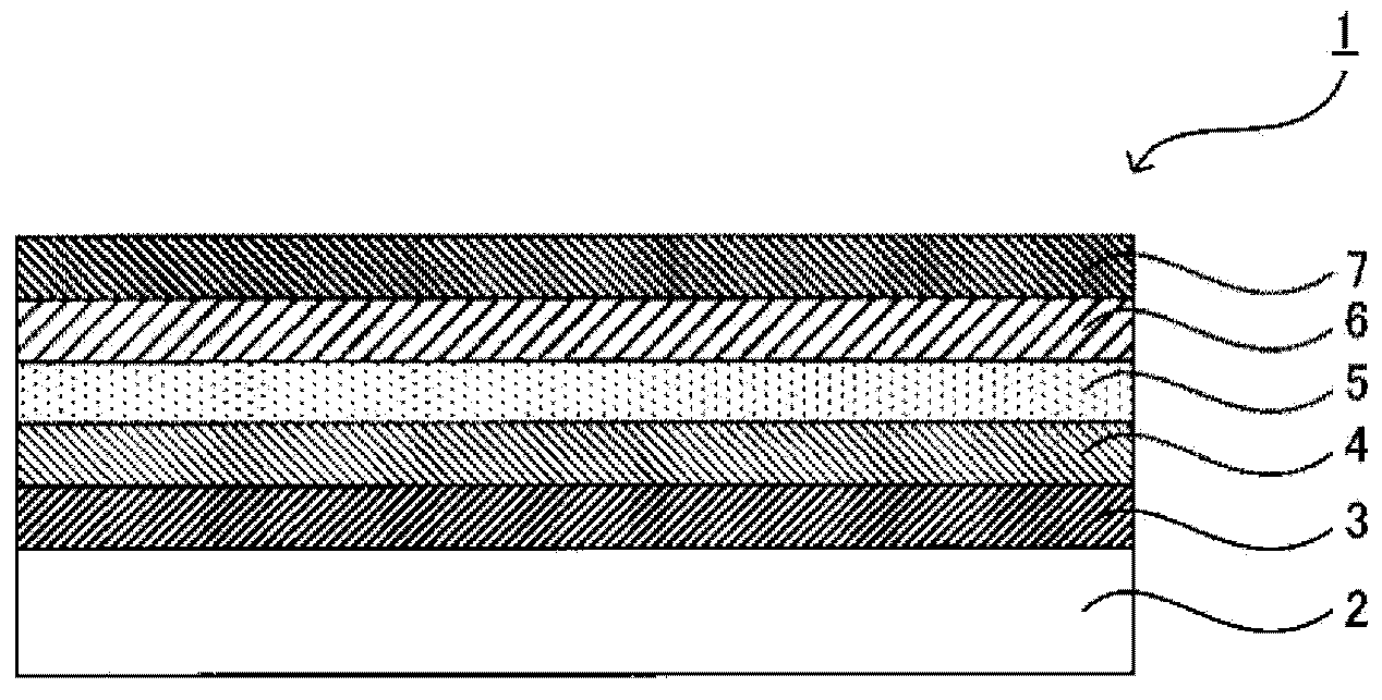
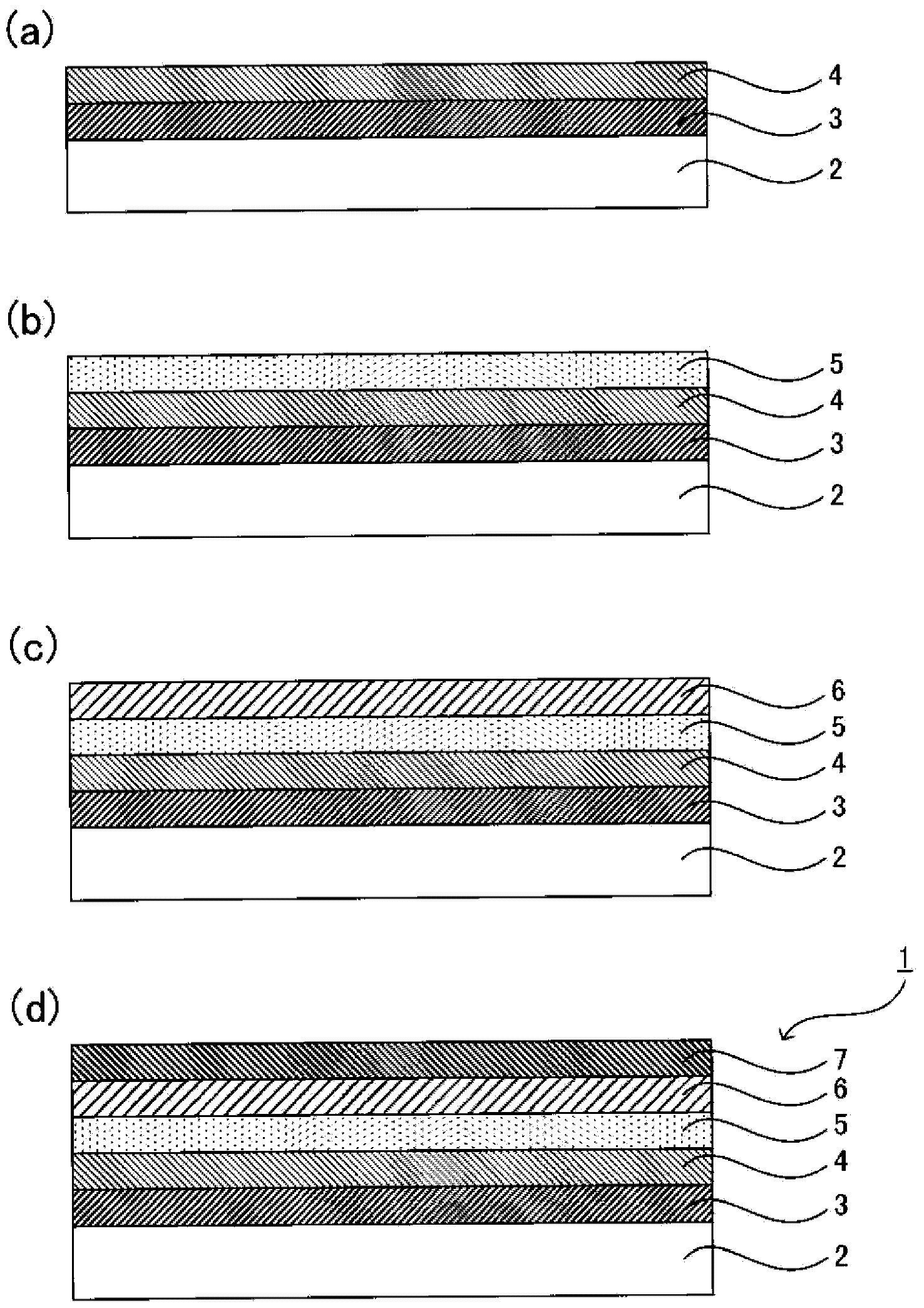
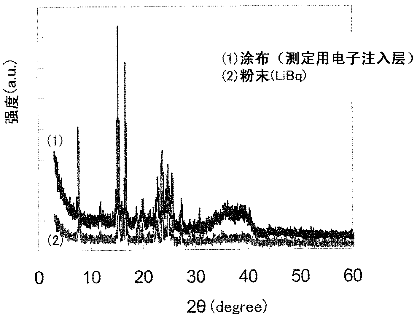
The main purpose of the present invention is to provide an organic EL element, which has an electron injection / transport layer containing an organic boron compound, and has excellent characteristics, such as efficiency and service-life. The present invention achieves the above-mentioned purpose by providing an organic EL element characterized in having: an anode; a light emitting layer, which is formed on the anode; an electron injection / transport layer, which is formed on the light emitting layer, contains an organic boron compound, and has a crystal structure; and a cathode, which is formed on the electron injection / transport layer.

Description

technical field [0001] The present invention relates to an organic electroluminescent element using an organoboron compound and a method for producing the same. Background technique [0002] Organic electroluminescence (hereinafter, electroluminescence is sometimes abbreviated as EL.) device in which an organic layer is sandwiched between a pair of electrodes and a voltage is applied between the two electrodes to make it emit light has the following advantages. High performance, excellent impact resistance because it is an all-solid-state element different from liquid crystal elements, fast response speed, less affected by temperature changes, and large viewing angle, etc., are attracting attention as light-emitting elements in display devices and lighting devices . [0003] As an organic EL element, an organic EL element in which multiple organic layers such as a hole injection and transport layer, a light emitting layer, and an electron injection and transport layer are l...

Claims


Application Information

Patent Timeline
Patent Type & Authority Applications(China)
IPC IPC(8): H01L51/50H05B33/10H05B33/26
CPCH10K71/12H10K85/322H10K50/166H10K50/171H10K50/16H10K85/60H10K85/6572H10K50/165
Inventor 乙木荣志上野滋弘
Owner DAI NIPPON PRINTING CO LTD
Learn More