
Crank gears for bicycles

A crank drive, bicycle technology, applied in the field of sensor systems, can solve problems such as not being able to withstand mechanical stress, and achieve the effect of a compact structure

Active Publication Date: 2017-09-12
ROBERT BOSCH GMBH
View PDF5 Cites 0 Cited by
  • Summary
  • Abstract
  • Description
  • Claims
  • Application Information

AI Technical Summary

Problems solved by technology

Furthermore, special materials are often required due to the necessary magnetization properties, which are more expensive than conventional materials such as steel and often cannot withstand the same mechanical stresses

Method used


Image

  • Crank gears for bicycles
  • Crank gears for bicycles
  • Crank gears for bicycles

Examples


Embodiment Construction

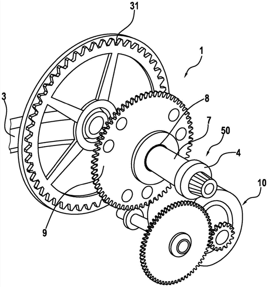
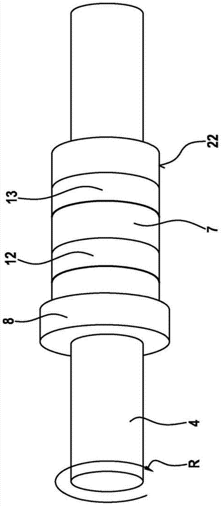
[0031] Refer below Figure 1 to Figure 5 , a crank gear 1 according to the invention for a bicycle and a bicycle with an electric auxiliary drive and a crank gear 1 of this type are described in detail on the basis of a first preferred embodiment.

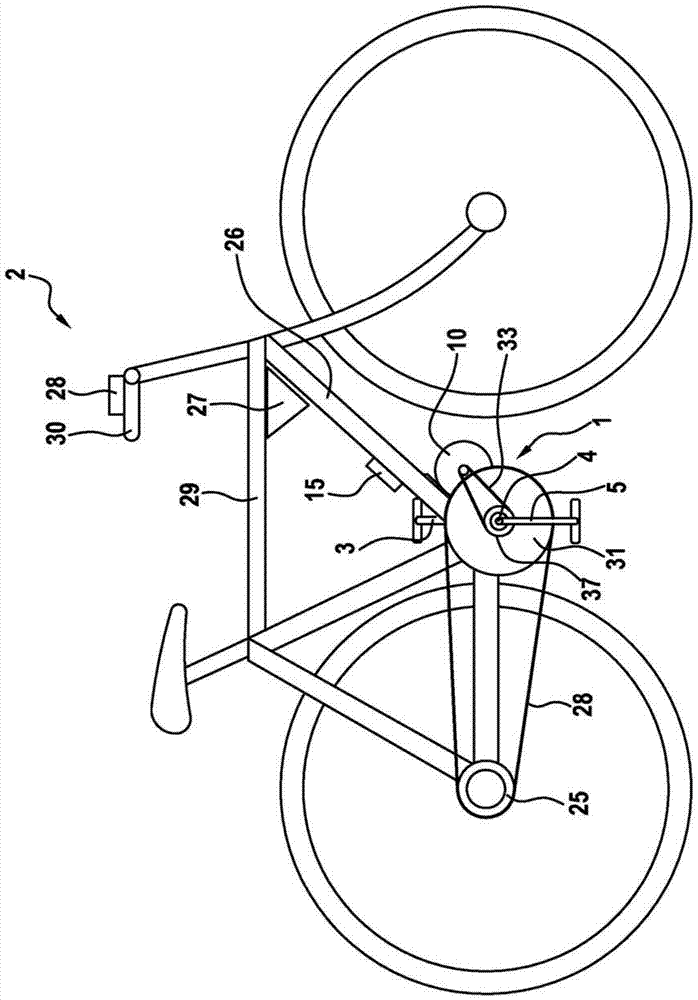
[0032] figure 1 A schematic illustration of a bicycle 2 with an integrated electrical auxiliary or central drive is shown. as from figure 1 It can be seen that the central drive comprises crank gear 1 , electric or electromotor auxiliary drive 10 , control unit 15 , operating unit 28 and rechargeable energy source 27 . The electric-motor auxiliary drive 10 is arranged below the down tube 26 and in front of the crank gear 1 of the bicycle 2 in the direction of travel and is fixed on the down tube 26 . The crank gear 1 has a pedal crankshaft 4 , to whose free end a pedal crank 3 or a pedal crank 5 is fastened. as from figure 1 It can further be seen that the control unit 15 is fastened to the down tube 26 and communicates with t...


PUM

PropertyMeasurementUnit
radiusaaaaaaaaaa

Abstract

The invention relates to a crank drive for a bicycle and to a bicycle with an electric motor auxiliary drive (10) and a crank drive (1) of this type, said crank drive comprising a pedal crankshaft ( 4), two pedal cranks (3, 5) and a torque sensor system (50) for detecting the torque applied to said pedal crank shaft (4), said pedal cranks being fixed to said pedal crank on the free end of the shaft (4), wherein the torque sensor system is designed as a piezoelectric sensor system (50).

Description

technical field [0001] The invention relates to a crank drive for a bicycle, a bicycle having such a crank drive and a sensor system. Background technique [0002] For bicycles with an auxiliary drive mechanism in the form of an electric motor (these bicycles are also called "Pedelecs" or electric bicycles) sensor systems are required which detect the cyclist's pedaling frequency (desire to drive) . The sensor system should ideally be integrated in the pedal crankshaft in order to keep the signal chain from the pedal crank to the sensor system as short as possible. Especially for better behavior when starting on hills, a sensor combination for pedaling frequency and torque is desirable. [0003] Since the pedal crankshaft of a bicycle involves a fully rotating shaft, a contactless sensor system is advantageous for reasons of service life. The pedaling frequency sensor (determining the rotational speed of the pedal crankshaft) can easily be implemented as a contactless mea...

Claims


Application Information

Patent Timeline
Patent Type & Authority Patents(China)
IPC IPC(8): G01L3/04
CPCB62M6/55B62M6/50G01L3/1442
Inventor R·斯塔文斯基
Owner ROBERT BOSCH GMBH
Learn More