
Antivibration apparatus

A technology for vibration isolation and mounting components, applied in the direction of non-rotational vibration suppression, springs made of plastic materials, springs, etc., to achieve the effects of improving durability, simplifying the bonding process, and reducing tensile input

Inactive Publication Date: 2013-12-18
SUMITOMO RIKO CO LTD
View PDF7 Cites 15 Cited by
  • Summary
  • Abstract
  • Description
  • Claims
  • Application Information

AI Technical Summary

Problems solved by technology

Furthermore, since precompression is given to the entire main body rubber elastic body by being sandwiched between the external mounting member and the restraint member, it is difficult to achieve a high degree of performance for each part when the characteristics required for each part of the main body rubber elastic body are different. The required characteristics

Method used


Image

  • Antivibration apparatus
  • Antivibration apparatus
  • Antivibration apparatus

Examples


Embodiment Construction

[0035] Hereinafter, embodiments of the present invention will be described with reference to the drawings.

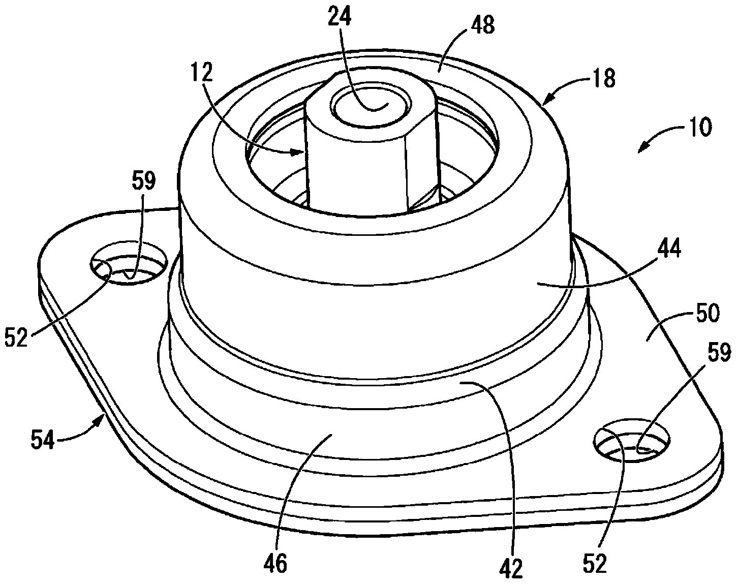
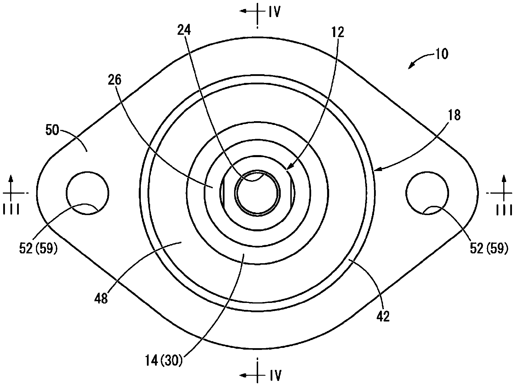
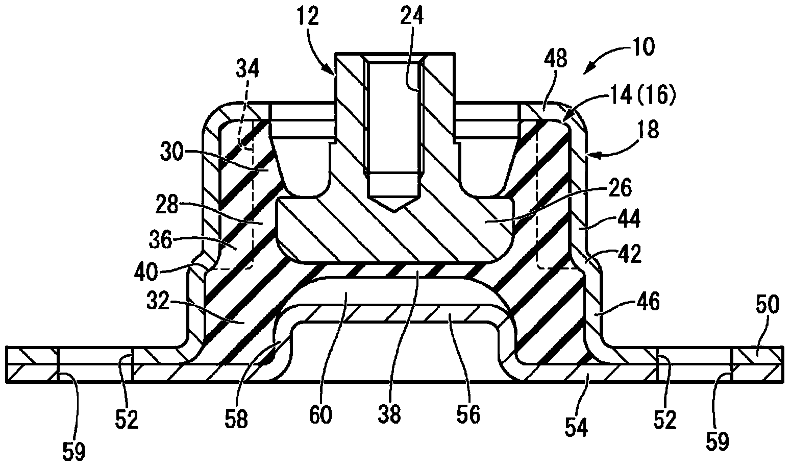
[0036] Figure 1 ~ Figure 4An engine mount 10 is shown as an embodiment of a vibration damping device designed according to the invention. The engine mount 10 has a structure in which the inner mounting member 12 and the outer mounting member are elastically connected by the main body rubber elastic body 14 by attaching the outer mounting member 18 to the integrally vulcanized molded product 16 having the main body rubber elastic body 14 of the inner mounting member 12 . 18. And, by installing the internal mounting member 12 on the power unit 20 (refer to Figure 9 ), and install the external mounting member 18 on the vehicle body 22 (see Figure 9 ), and the power unit 20 is vibration-isolated and supported on the vehicle body 22 . In addition, in the following description, unless otherwise specified, the vertical direction refers to the axial direction, that is, ...


PUM


Abstract

Provided is an antivibration apparatus having a novel structure allowing separate adjustment of each spring on a main rubber elastic body according to the required spring characteristics. An outer circumferential linking rubber (28) and a first and second axial-direction projecting rubber (30, 32) are formed on the main rubber elastic body (14). An outer attachment member (18) is provided on both sides of a stepped part (42) with a small-diameter cylinder (44) and a large-diameter cylinder (46), an inward-projecting part (48) being formed in the opening of the small-diameter cylinder (44) and an inner circumferential cylinder wall (58) being formed on a restraining member (54) affixed to the opening of the large-diameter cylinder (46). The outer circumferential linking rubber (28) is disposed in the space facing the direction perpendicular to the axis of an inner attachment member (12) and the inward-projecting part (48). The first axial-direction projecting rubber (30) is held by compression in the axial direction between the inner attachment member (12) and the inward-projecting part (48). The second axial-direction projecting rubber (32) is held by compression in the axial direction between the restraining member (54) and the inner attachment member (12) and stepped part (42), and is also held by compression in the direction perpendicular to the axis between the inner circumferential cylinder wall (58) and the large-diameter cylinder (46).

Description

technical field [0001] The present invention relates to a vibration isolating device used, for example, as an engine mount of an automobile or the like. Background technique [0002] Conventionally, a vibration isolator used as an engine mount or the like of an automobile is known. This vibration isolator has a structure in which an inner mounting member and a cylindrical outer mounting member are elastically connected by a main body rubber elastic body. For example, the inner mounting member is attached to a power unit and the outer mounting member is attached to a vehicle body. The power unit is vibration-isolated and supported on the body. [0003] In addition, in the vibration isolator, the rubber elastic body of the main body is usually vulcanized and bonded to the inner mounting member and the outer mounting member, and the inner mounting member and the outer mounting member are pretreated for bonding (grinding of the bonded part, etc.) . On the other hand, in order...

Claims


Application Information

Patent Timeline
Patent Type & Authority Applications(China)
IPC IPC(8): F16F15/08F16F1/38
CPCF16F1/373
Inventor 水川弘树清水赖重市川浩幸
Owner SUMITOMO RIKO CO LTD
Learn More