
Patsnap Eureka
For R&D, Patsnap Eureka makes reading and utilizing patents & technical documents easy.
Patsnap Eureka AIR
Designed for self-driven R&D workflows. Generate viable solutions, solve complex R&D challenges, empower your innovation with AI.

Patsnap Eureka Materials
Designed for material experts only. Revolutionize your material R&D, from search, analyze, to developing new materials.

TechResearch
Generate reliable direction feasibility study reports for your R&D in just a few steps.

TechSeek
Discover and master advanced knowledge NOW. Basics, ideas, possibilities, all at once.

TechMind
As an expert in R&D Theories, TechMind can generates customized viable solutions instantly.

TechRisk
Analyze your overall solution with one click, know your potential R&D risks in advance.

TechMonitor
Get weekly tech updates, stay abreast of the latest tech innovations and key insights.
Washing device for porous hollow fiber membranes, and porous hollow fiber membrane production method
A technology of cleaning device and manufacturing method, applied in fiber processing, chemical instruments and methods, rayon cleaning/drying, etc., can solve the problem of concentration drop, etc., to prevent re-adhesion, reduce the concentration of residual substances, and restrain the usage amount. Effect
- Summary
- Abstract
- Description
- Claims
- Application Information
AI Technical Summary
Problems solved by technology
Method used
Image

Examples
Embodiment approach
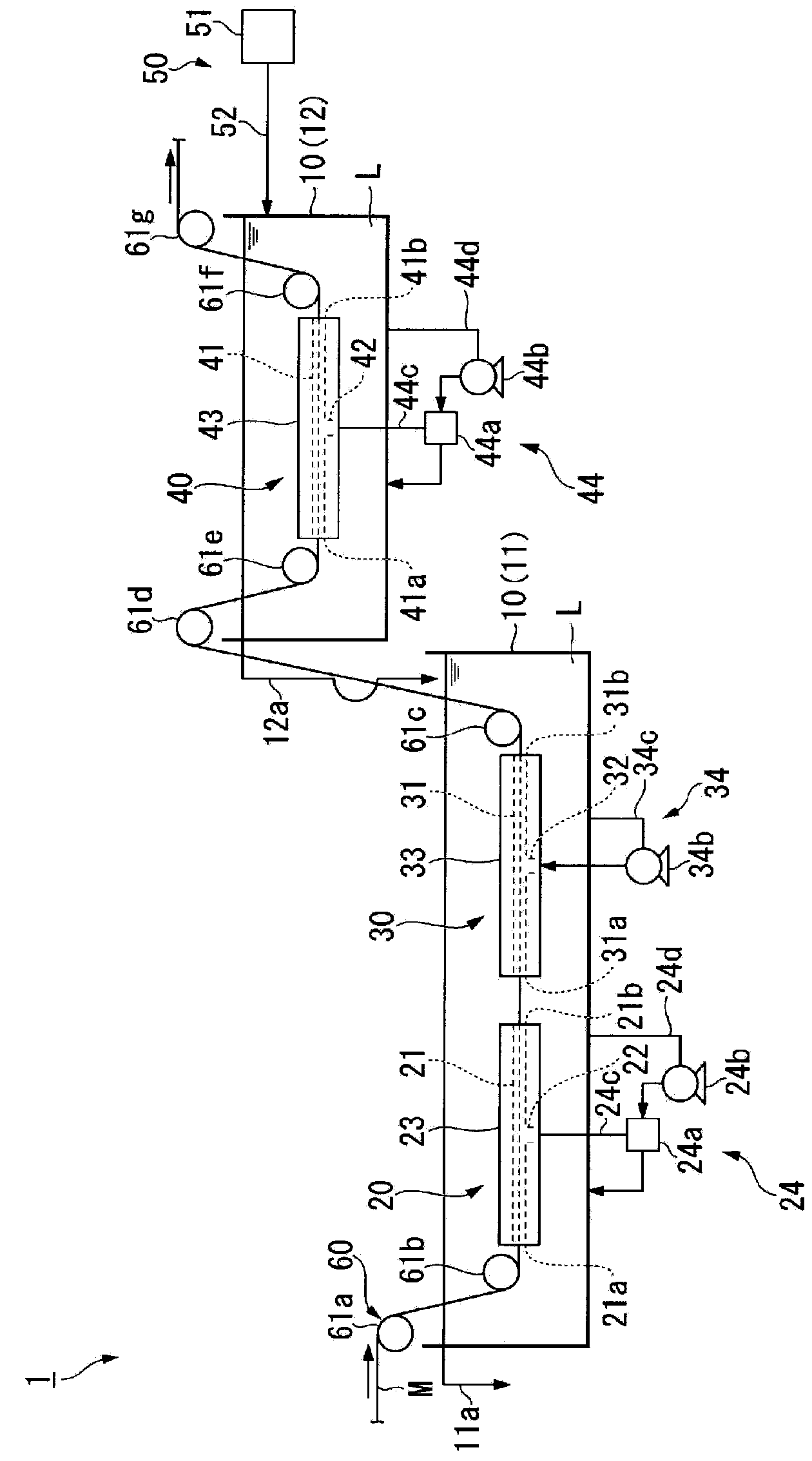
[0155] The cleaning device of the present invention is not limited to figure 1 The cleaning device 1 shown. For example, in the cleaning device 1, the entire flow path members 23, 33, 43 are immersed in the cleaning liquid L, but only the openings 21a, 21b, 31a, 31b, 41a, 31b, 41a, 31b, 41a, 41b is arranged in the cleaning liquid L so that each flow path is filled with the cleaning liquid L, and is not limited to the form in which the entire flow path members 23, 33, 43 are immersed in the cleaning liquid L.
[0156] In addition, the hollow fiber membrane travel channel 31 of the pressurized cleaning unit 30 is filled with the cleaning liquid L pushed in from the branch channel 32 by the liquid injection unit 34 , and the cleaning liquid L passes through the hollow fiber membrane travel channel 31 from both sides. The openings 31a, 31b of the ends are discharged.
[0157] In addition, the liquid suction units 24, 44 of the first decompression cleaning part 20 and the second ...
Embodiment 1
[0289] (solidification process)
[0290] As in the mass ratio shown in Table 1, polyvinylidene fluoride A (manufactured by Atofina Japan, trade name Kaina-301F), polyvinylidene fluoride B (atofina Japan) Na Japan, trade name Kaina-9000LD), polyvinylpyrrolidone (ISP company, trade name K-90) and N, N-dimethylacetamide were mixed separately to prepare the membrane stock solution (1) and Membrane stock solution (2).
[0291] Next, prepare such a nozzle: the center is formed with a hollow portion, and on its outside, double annular discharge ports are sequentially formed so that two kinds of liquids can be coated sequentially (referring to Japanese Patent Application Laid-Open No. 2005-42074). figure 1 ), with the nozzle kept warm at 30°C, a polyester multifilament monofilament braid (multifilament; 830T / 96F, 16 counts) was introduced into the hollow part as a porous substrate, and the outer circumference was measured from the inside. Sequentially apply the film-making stock sol...
Embodiment 2
[0329] A hollow fiber membrane was produced in the same manner as in Example 1 except that the supply rate of the washing liquid was 1000 g / min.
PUM
 Abstract
Description
Claims
Application Information
 - R&D Engineer
- R&D Manager
- IP Professional
- Industry Leading Data Capabilities
- Powerful AI technology
- Patent DNA Extraction
Browse by: Latest US Patents, China's latest patents, Technical Efficacy Thesaurus, Application Domain, Technology Topic, Popular Technical Reports.
© 2024 PatSnap. All rights reserved.Legal|Privacy policy|Modern Slavery Act Transparency Statement|Sitemap|About US| Contact US: help@patsnap.com