Seedling transplanting machine

A technology for transplanting machines and seedlings, which is applied in the field of seedling transplanting machines, which can solve the problems of inability to supply seedlings, increase the rotational load, and difficulty in reaching the cultivation depth adjustment rod, etc., and achieve the effect of simple and cheap production and reduced resistance

Active Publication Date: 2016-01-06
KUBOTA CORP
View PDF7 Cites 0 Cited by
  • Summary
  • Abstract
  • Description
  • Claims
  • Application Information

AI Technical Summary

Problems solved by technology

[0008] In the aforementioned prior art, since a ratchet wheel is also installed on the central axis of the supporting turntable, therefore, when the arrangement number of the rice shoot supply body is large or the distance from the central axis to the rice shoot supply body becomes long, the surrounding parts of the turntable The weight increases, and the rotational load increases, sometimes it is difficult to drive with the seedling supply drive rod
[0009] In the aforementioned prior art, although the closing bar of the shutter is arranged at the same height in the whole length, the shutter can be opened to make the seedling fall, but the upper mouth of the rice seedling supply body expands into a trumpet shape, and when the leaves of the rice seedling expand When it comes, it will be hooked on the upper mouth, and the seedlings will fall at different times, and the seedlings may not be supplied smoothly.
[0010] In the aforementioned prior art, since the cultivation depth adjustment lever is arranged near the driver's feet below the control handle, it is easy to adjust the cultivation depth while operating the control handle. When the seedlings are supplied to the seedling supply body, it is difficult to reach the cultivation depth adjustment rod with hands, and the seedling transplanter must be temporarily stopped to adjust the cultivation depth

Method used


Image

  • Seedling transplanting machine
  • Seedling transplanting machine
  • Seedling transplanting machine

Examples


Embodiment Construction

[0078] Embodiments of the present invention will be described below with reference to the drawings.

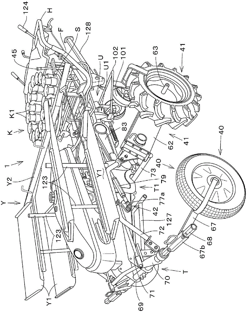
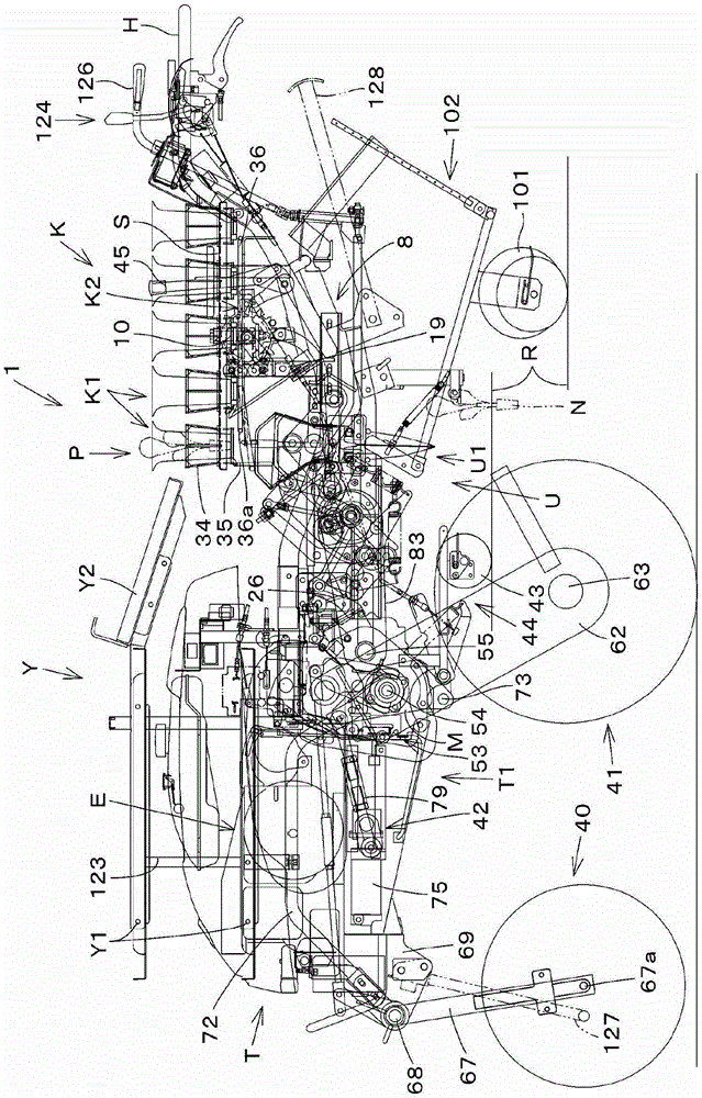
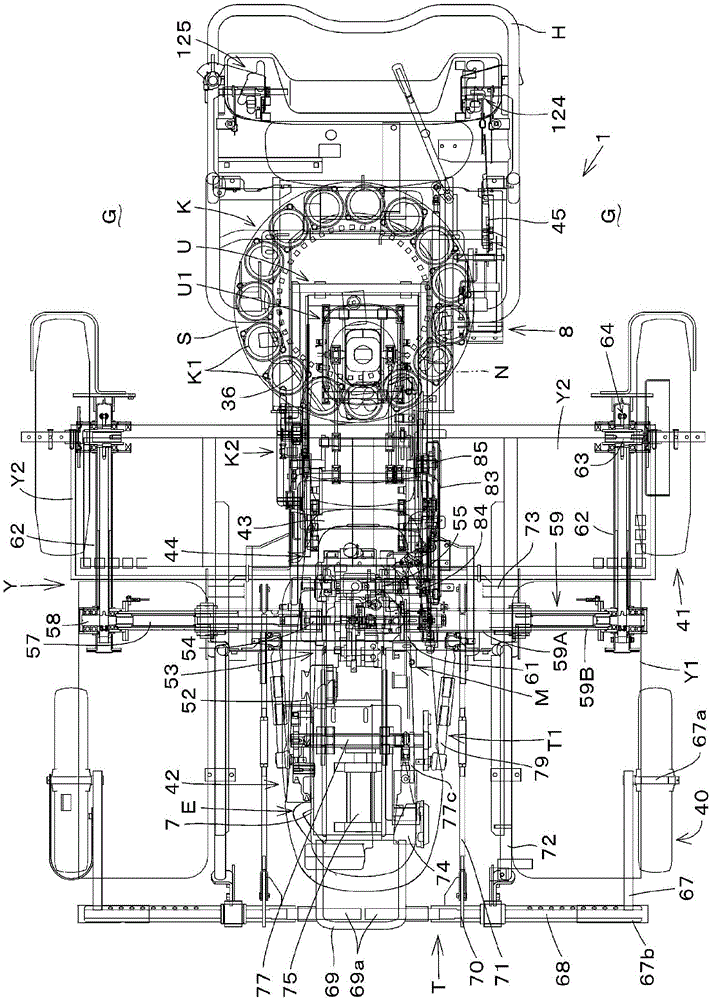
[0079] exist Figure 1~3 1 shows an example of a walking-type seedling transplanter 1 that moves along the longitudinal direction across the ridge R and cultivates unit-shaped seedlings such as tobacco seedlings and vegetables, seedlings with soil blocks, and seedlings in pots at predetermined intervals.

[0080] This seedling transplanting machine 1 generally has: a mobile body T that can travel; a rice shoot cultivation device U installed on the rear portion of the mobile body T; The seedling supply device K of the device U;

[0081] The platform 7 of the mobile body T protrudes forward from the transmission M, and an engine (drive source) E is mounted on the top thereof. The rear end of the frame 8 is connected with the joystick H, and the front wheel (front traveling device) 40 and the rear wheel (rear traveling device) 41 are suspended by the gearbox M and the platform ...


PUM


Abstract

Provided is a rice shoot transplanter, which is disposed above a rice shoot cultivation device. A rice shoot supply device supplying the rice shoot to the rice shoot cultivation device comprises a rotating bench which rotates freely around a vertical shaft, a plurality of rice shoot feeding machine which are disposed at the periphery of the rotating bench and are capable of receiving the rice shoots, and a supply driving mechanism which moves simultaneously with the up-and-down movement of the rice shoot cultivation device and drives the rotating bench. As for the supply driving mechanism, clamping parts are arranged in a circular shape near the rice shoot feeding machine of the rotating bench. The lower part of the rotating bench is provided with a clamping rotation body which is clamped with the clamping part and rotates and drives the rotating bench. A feeding link mechanism rotating the clamping rotation body is connected to a cultivation driving mechanism of the rice shoot cultivation device. The rice shoot transplanter is advantageous in that the rotating bench can be directly rotated and driven at the position away from the vertical shaft; rice shoots can successfully fall from a feeding cup; rice shoots can be fed while cultivation depth can be easily adjusted.

Description

technical field [0001] The invention relates to a seedling transplanting machine for transplanting tobacco seedlings, lettuce seedlings and the like. Background technique [0002] As disclosed in Patent Document 1, the rice seedling transplanting machine has a rice seedling cultivating tool that periodically protrudes into the field surface soil, and when protruding, the lower end side is opened to form a hole for seedling cultivation in the field surface soil, and is configured as follows: The seedlings supplied to the inner space of the seedling cultivating tool fall into the hole for seedling cultivation when the lower end side of the seedling cultivating tool is opened, and are cultivated. And the cylindrical seedling guide which guides the seedling supplied from this seedling supply body to the internal space of the said seedling cultivation tool (claims). [0003] And the seedling supply device is constituted as: a plurality of seedling supply bodies are arranged at e...

Claims


Application Information

Patent Timeline
Patent Type & Authority Patents(China)
IPC IPC(8): A01C11/02
Inventor 福冈和树野坂健吉
Owner KUBOTA CORP
Why Eureka
Try Eureka