
Method for preparing functionalized composite nano-fiber modified electrode

A technology of composite nanofibers and modified electrodes, which is applied in the direction of electrochemical variables of materials, material analysis by electromagnetic means, and measurement devices, etc. Related literature reports and other issues

Active Publication Date: 2013-12-11
SOUTHEAST UNIV
View PDF0 Cites 13 Cited by
  • Summary
  • Abstract
  • Description
  • Claims
  • Application Information

AI Technical Summary

Problems solved by technology

[0003] At present, the application of carbon materials [1-3] ,Metal oxide [4] ,Polymer Materials [5] wait for a single [6] ,complex [7,8] There are many reports on the modification of various electrodes by nanofibers, but there are common problems such as poor conductivity, stability and biocompatibility of nanofibers, and the specific surface area of ​​modified electrodes is not significantly enlarged.
If it is possible to dope nanomaterials with good conductivity (carboxylated multi-walled carbon nanotubes) and spinnable polymers with good stability (nylon 6) to obtain a precursor electrospinning solution, and obtain conductive composite nanofibers through electrospinning Modified electrodes; and then electrically modified (electropolymerized thionine monomer) to wrap a layer of conductive composite nanofibers with a porous 3D structure and conductive polymers carrying a large number of active groups, thereby obtaining functional composite nanofibers. There are no relevant literature reports on the method of fiber electrode modification materials at home and abroad

Method used


Image

  • Method for preparing functionalized composite nano-fiber modified electrode
  • Method for preparing functionalized composite nano-fiber modified electrode
  • Method for preparing functionalized composite nano-fiber modified electrode

Examples


Embodiment Construction

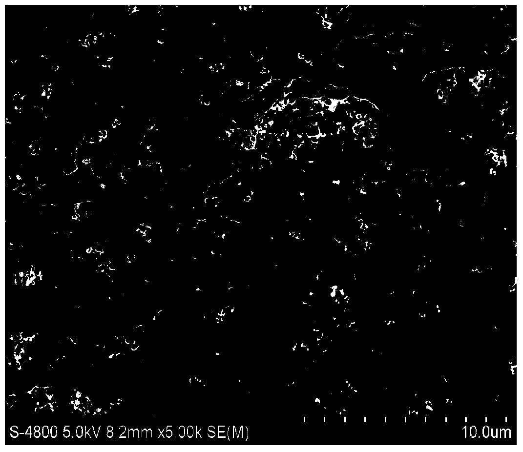
[0048] The microscopic morphology of PA6-MWNTs and PA6-MWNTs-PTH were characterized respectively. From the field emission scanning electron microscopy (FESEM) of PA6-MWNTs ( figure 1 , figure 2 ) It can be seen that the random orientation of PA6-MWNTs forms a nanofiber membrane with a porous 3D structure. After electropolymerization of thionine PTH on PA6-MWNTs nanofibers ( image 3 , Figure 4 ), the diameter of the nanofibers becomes significantly thicker, ranging from 100 nm to 500 nm in diameter. It can be seen from the enlarged map that the surface of the nanofiber is no longer smooth, and the surface is obviously covered with a film. From the comparison of the microscopic morphology of nanofibers before and after electropolymerization of thionine, it can be concluded that a layer of thionine has been successfully electropolymerized on the surface of nanofibers.

[0049] The bare glassy carbon electrode (GC) and the composite nanofiber modified electrode (PA6-MWNTs / ...


PUM

PropertyMeasurementUnit
diameteraaaaaaaaaa
diameteraaaaaaaaaa

Abstract

The invention relates to method for preparing a functionalized composite nano-fiber modified electrode. The method specifically comprises the steps of (1) preparing a spinning solution; (2) preparing composite nano-fibers through electrostatic spinning so as to form a composite nano-fiber PA6-MWNTs modified electrode; (3) carrying out electrical-polymerization thionine functionalization on the composite nano fibers: soaking the composite nano-fiber PA6-MWNTs modified electrode into a polymerization solution containing thionine monomers PTH, applying a voltage to the modified electrode so as to carry out anodizing treatment, then, carrying out cyclic volt-ampere scanning, washing away the thionine monomers, adsorbed to the modified electrode, by using a phosphate buffer solution PBS, forming a functionalized composite nano-fiber electrode modification material PA6-MWNTs / PTH layer on the surface of the electrode after the polymerization reaction is ended, thus obtaining the functionalized composite nano-fiber PA6-MWNTs / PTH modified electrode. According to the method, a functionalized composite nano-fiber electrode modification material which has the characteristics of good stability, large specific surface area, good biocompatibility, high electron transfer rate, uniformly-distributed diameter and pore size, and the like is obtained.

Description

technical field [0001] The invention discloses a preparation method of a functional composite nanofiber modified electrode. The invention belongs to the field of nanometer material modified electrodes. Background technique [0002] Electrospinning modified electrodes is a method of modifying electrodes that has only emerged in recent years, and it has great potential for development. So far, electrospinning modified electrodes can be roughly divided into two categories according to different modification methods: electrospinning directly modified electrodes and indirect modified electrodes. Direct electrospinning electrode modification refers to the use of bare electrodes instead of traditional fiber receiving screens to directly collect the electrospun fibers on the electrode surface. The fiber-modified electrode obtained by this modification method can be applied to electrochemical and biosensors. Electrospinning non-direct modification of electrodes refers to the prepa...

Claims


Application Information

Patent Timeline
Patent Type & Authority Applications(China)
IPC IPC(8): G01N27/327G01N27/48
Inventor 王晓英
Owner SOUTHEAST UNIV
Learn More