
High-precision measuring device for measuring joint type equipment member bar deformation

A measuring device, high-precision technology, applied in the direction of measuring devices, optical devices, instruments, etc., to achieve the effect of light weight, ensuring stability, and high resolution

Inactive Publication Date: 2013-12-11
HEFEI UNIV OF TECH
View PDF9 Cites 7 Cited by
  • Summary
  • Abstract
  • Description
  • Claims
  • Application Information

AI Technical Summary

Problems solved by technology

[0005] The purpose of the present invention is to provide a high-precision measuring device for measuring the deformation of joint equipment rods to solve the problems in the prior art

Method used


Image

  • High-precision measuring device for measuring joint type equipment member bar deformation
  • High-precision measuring device for measuring joint type equipment member bar deformation

Examples


Embodiment Construction

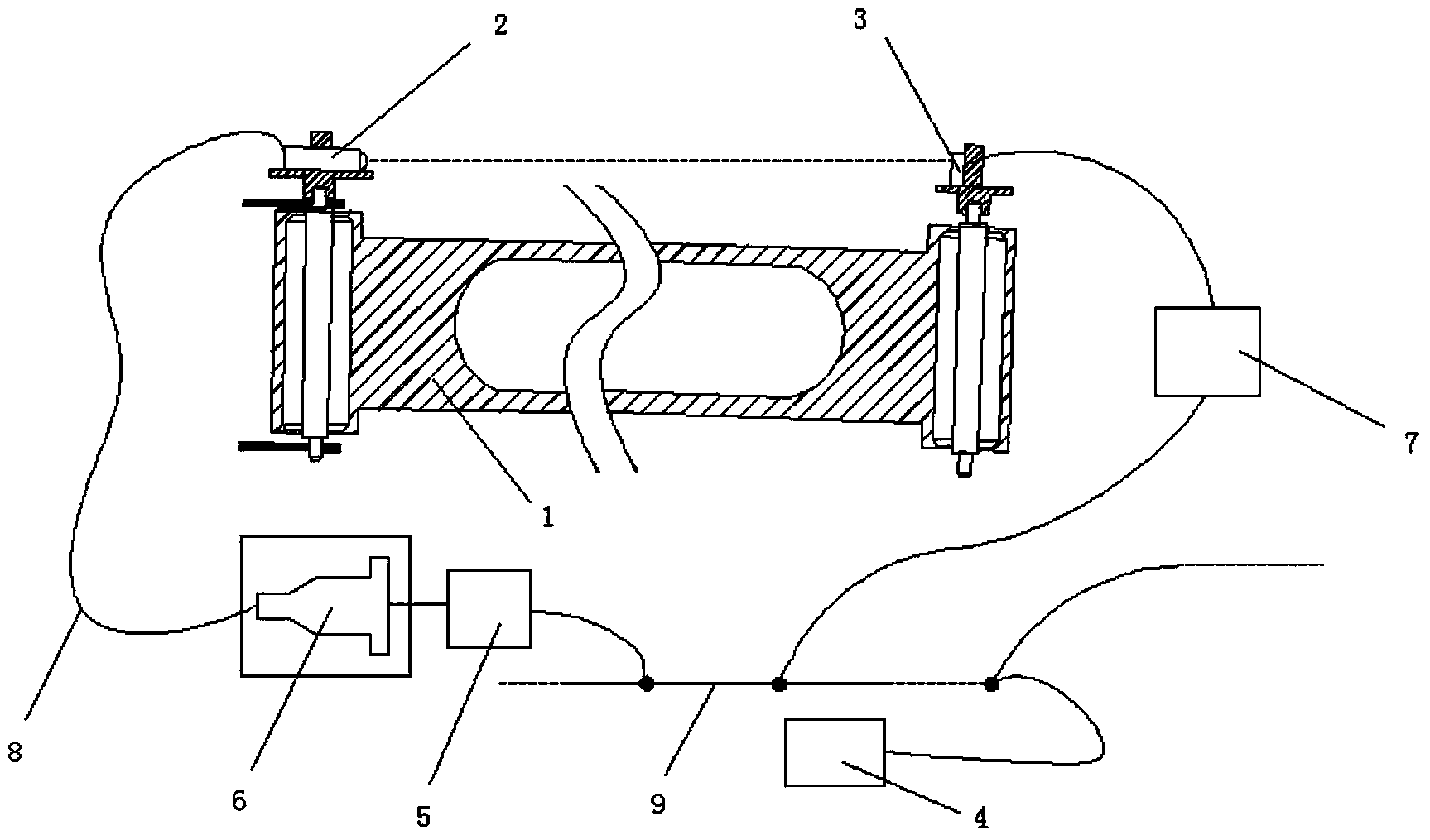
[0021] Such as figure 1 shown. A high-precision measuring device for measuring the deformation of a bar of joint equipment, comprising an optical head 2 arranged on the top of one end of a bar 1 of a parallel double-joint coordinate measuring machine, and an optical head 2 arranged on the top of the other end of the bar 1 of a parallel double-joint coordinate measuring machine The photosensitive surface 3, the optical head 2 is opposite to the photosensitive surface 3, and also includes a main control circuit 4, a laser drive unit 5, a laser diode 6, a signal detection circuit 7, and the signal detection circuit 7 and the laser drive unit 5 respectively adopt the IIC bus 9 The photosensitive surface 3 is connected to the input terminal of the signal detection circuit 7, the input terminal of the laser diode 6 is connected to the output terminal of the laser drive unit 5, and the output beam from the output terminal of the laser diode 6 is coupled to the optical head 2 through ...


PUM


Abstract

The invention discloses a high-precision measuring device for measuring joint type equipment member bar deformation. The high-precision measuring device for measuring joint type equipment member bar deformation is a real-time error compensation device aiming at solving the problem that an armed lever member bar deforms elastically in the measuring process of the geometric dimension of a parallel dual-joint coordinate measuring machine. The high-precision measuring device for measuring joint type equipment member bar deformation is based on the laser detection principle and combined with the elastic deformation of an electronic circuit detection armed lever relative to a reference beam, and on-line correction of the error is achieved. The high-precision measuring device for measuring joint type equipment member bar deformation is easy to assemble, convenient and fast to use, light and handy in structure and easy to operate. By means of the high-precision measuring device for measuring joint type equipment member bar deformation, the measuring error of the parallel dual-joint coordinate measuring machine can be well corrected, and therefore measuring precision is improved.

Description

technical field [0001] The invention relates to the field of error measuring devices for parallel double-joint coordinate measuring machines, in particular to a high-precision measuring device for measuring the deformation of rods of joint equipment. Background technique [0002] The parallel double-joint coordinate measuring machine is based on a non-orthogonal coordinate system, and is mainly composed of a mobile platform in the vertical direction, a displacement scale, and a measuring arm that can rotate freely in the X-Y plane. The Z-axis system is mainly composed of motor, lead screw, double parallel guide rails, long grating and other parts. The motor drives the measuring arm to move vertically along the guide rail through the lead screw, and the long grating records its moving distance; the measurement in the XY plane requires an instrument There are 2 degrees of freedom in the horizontal plane, which are realized by 2 rotating joints in the measuring arm. The whole ...

Claims


Application Information

Patent Timeline
Patent Type & Authority Applications(China)
IPC IPC(8): G01B11/16
Inventor 于连栋鲁思颖赵会宁杜芸董钊陆洋韩丽玲
Owner HEFEI UNIV OF TECH
Learn More