High-precision positioning device for reinforcement straightening cutting-off machine

A technology of positioning device and cutting machine, applied in the field of steel bar straightening and cutting machine, can solve the problems of steel bar cutting length error, increase production cost, affect product quality, etc., and achieve the effects of safe and convenient use, improved work efficiency, and simple structure

Inactive Publication Date: 2013-12-11
安徽天宇金属股份有限公司
View PDF5 Cites 2 Cited by
  • Summary
  • Abstract
  • Description
  • Claims
  • Application Information

AI Technical Summary

Problems solved by technology

[0002] At present, the domestic steel bar straightening and cutting machine only installs a proximity switch device for controlling the cutting length of the steel bar on the runway guide rail of the steel bar. Finally, when running at high speed from left to right in the steel bar running groove, when the right end of the steel bar touches the touch panel in the proximity switch device, the touch panel is separated from the proximity switch through the rotating shaft. At this time, the circuit is closed and the signal Output, the steel bar cutting machine operates, but there is still 0.2 seconds in the process from the separation of the proximity switch to the cutting of the steel bar. At this time, the steel bar is still moving forward with an inertia of more than 100 meters per minute, and the speed is not equal. Due to the Inertial motion and unequal speed, which will easily cause errors in the length of steel bar cutting, which not only affects product quality, but also increases production costs

Method used


Image

  • High-precision positioning device for reinforcement straightening cutting-off machine
  • High-precision positioning device for reinforcement straightening cutting-off machine
  • High-precision positioning device for reinforcement straightening cutting-off machine

Examples


Embodiment Construction

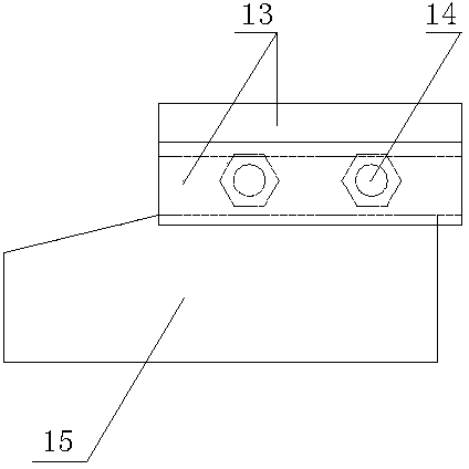
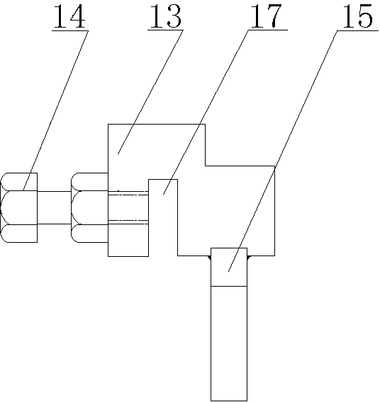
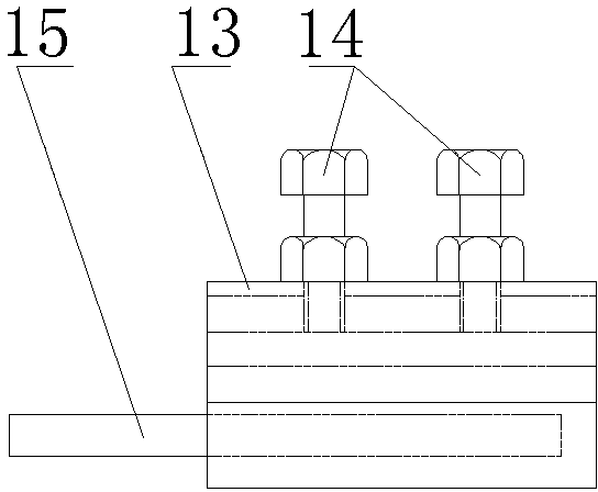
[0017] From Figure 1-Figure 6 As can be seen in the figure: a high-precision positioning device for a steel bar straightening and cutting machine (referred to as a high-precision positioning device), including a main box 18 of a steel bar straightening and cutting machine, a frame 19 and a guide rail 12 for installing the high-precision positioning device, This guide rail 12 is installed on the upper part of the frame 19 located on the right side of the main chassis 18. It is characterized in that: the high-precision positioning device for the steel bar straightening and cutting machine also includes a baffle base 13, a baffle 15 and a fixing bolt II 14. The baffle seat 13 is a cuboid, and the front upper part of the baffle seat 13 is provided with a rectangular straight-through slit left and right. card slot 17, and make the groove width of the straight-through card slot 17 slightly larger than the width of the guide rail 12, and set left and right screw holes on the rear wa...


PUM


Abstract

The invention relates to a high-precision positioning device for a reinforcement straightening cutting-off machine and belongs to a reinforcement straightening cutting-off machine. The high-precision positioning device is characterized by also comprising a baffle seat body, a baffle and fixing bolts II, wherein the baffle seat body is a cuboid; the front upper part of the baffle seat body is transversely provided with a rectangular through undercut groove; the rear lower part of the baffle seat body is transversely provided with a through clamping groove; the groove width of the through clamping groove is slightly greater than the width of a guide rail; the rear groove wall of the through clamping groove is uniformly provided with left and right screw holes, and the fixing bolts II are correspondingly screwed in the left and right screw holes; the front bottom part of the baffle seat body is transversely provided with a rectangular straight slot, and the rectangular baffle which is vertically arranged is correspondingly embedded into the rectangular straight slot and is welded with the rectangular straight slot into one whole body; the left section of the baffle extends out of the baffle seat body. When in use, the high-precision positioning device is fixedly arranged on the guide rail, and the baffle is correspondingly positioned in an operation groove of a reinforcement, so that accuracy of the fabrication length of the reinforcement is ensured, and production efficiency is improved.

Description

technical field [0001] The invention belongs to a steel bar straightening and cutting machine, in particular to a positioning device for a steel bar straightening and cutting machine. Background technique [0002] At present, the domestic steel bar straightening and cutting machine only installs a proximity switch device for controlling the cutting length of the steel bar on the runway guide rail of the steel bar. When the steel bar is straightened and runs at high speed from left to right in the steel bar running groove, When the right end of the steel bar touches the touch panel in the proximity switch device, the touch panel is separated from the proximity switch through the rotating shaft. At this time, the circuit is closed, the signal is output, and the steel bar cutting machine operates, but it is separated from the proximity switch to the steel bar. After being cut off, there is still 0.2 seconds for this process. At this time, the steel bar is still moving forward ...

Claims


Application Information

Patent Timeline
Patent Type & Authority Applications(China)
IPC IPC(8): B21F11/00
Inventor 汪国华彭仲平
Owner 安徽天宇金属股份有限公司
Why Eureka
Try Eureka