
Semi-blind oversampling clock data recovery circuit with high locking range

A technology for clock data recovery and locking range, which is applied in the direction of electrical components, automatic power control, etc., can solve the problem of low locking range, and achieve the effect of improving the locking range, increasing the locking range, and reducing the workload

Active Publication Date: 2013-12-04
NANJING UNIV OF POSTS & TELECOMM INST AT NANJING CO LTD
View PDF2 Cites 6 Cited by
  • Summary
  • Abstract
  • Description
  • Claims
  • Application Information

AI Technical Summary

Problems solved by technology

JournalOfSolid-StateCircuits上于2007年发表的A3.2Gb / sCDRUsingSemi-BlindOversamplingtoAchieveHighJitter Tolerance和A40–44Gb / s3×OversamplingCMOSCDR / 1:16DEMUX以及JOURNALOF SELECTEDTOPICSINQUANTUMELECTRONICS上于2010年发表的5 / 10-Gb / sBurst-Mode ClockandDataRecoveryBasedonSemiblindOversamplingforPONs:Theoreticaland Experimental can see that the structures of these semi-blind oversampling clock data recovery circuits are basically similar, and the obtained data rate locking ranges are 1.9Gbps-3.5Gbps, 39.96Gbps-44.42Gbps, and 242M respectively. It can be seen that compared to The resulting lock range is not high for its recoverable maximum data rate

Method used


Image

  • Semi-blind oversampling clock data recovery circuit with high locking range
  • Semi-blind oversampling clock data recovery circuit with high locking range
  • Semi-blind oversampling clock data recovery circuit with high locking range

Examples


Embodiment Construction

[0018] In order to further illustrate the advantages of the present invention and the specific technical means adopted, the specific implementation and circuit structure of the present invention will be described in detail below in conjunction with the drawings.

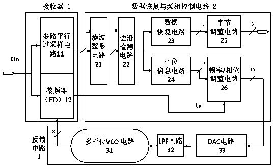
[0019] figure 1 The semi-blind oversampling clock data recovery circuit with a high locking range is shown, which includes a receiver 1 composed of multiple parallel oversampling circuits 11 and a frequency discriminator FD12; a filter shaping circuit 21, an edge detection circuit 22, The data recovery and frequency phase control circuit 2 composed of data recovery circuit 23, phase information circuit 24, byte adjustment circuit 25 and frequency / phase adjustment circuit 26, the feedback circuit composed of multi-phase VCO circuit 31, LPF circuit 32 and DAC circuit 33 Circuit 3.

[0020] The input terminal of the frequency discriminator FD12 is connected to the input signal Din, the output signal up is connected to ...


PUM


Abstract

The invention discloses a semi-blind oversampling clock data recovery circuit with a high locking range, which is mainly used for improving the range of application of the semi-blind oversampling clock data recovery circuit and avoiding generating error code during excessive continuous word time data recovery. The semi-blind oversampling clock data recovery circuit comprises a receiver (1) composed of a multi-path parallel oversampling circuit (11) and a frequency detector FD (12), a data recovery and frequency phase control circuit (2) composed of a filtering and shaping circuit (21), an edge detection circuit (22), a data recovery circuit (23), a phase information circuit (24), a byte adjustment circuit (25) and a frequency / phase adjustment circuit (26), and a feedback circuit (3) composed of a multi-phase VCO (Voltage Controlled Oscillator) circuit (31), a LPF (Low Pass Filter) circuit (32) and an DAC (Digital to Analog Converter) circuit (33). Through the adjustment, the frequency of the sampling clock just can sample the input data, the locking is realized, and the clock data recovery is further accomplished.

Description

technical field [0001] The invention relates to the technical field of semiconductor integrated circuit design, in particular to a clock data recovery circuit (CDR) for serial communication. Background technique [0002] As an important part of the receiving end, the clock data recovery circuit (CDR) is responsible for extracting synchronous information from high-speed serial data, and using this synchronous information to sample the serial signal to recover the correct digital signal, and realize serial parallel to the data convert. Generally speaking, when serial data is sent to the transmission medium at the sending end, the characteristics of the data signal are ideal. At the receiving end, the data signal arriving through the transmission medium is superimposed by external noise and interference. When the receiving end extracts data from the serial data, it must select the best sampling decision time to ensure the minimum bit error rate. In view of such a situation, ...

Claims


Application Information

Patent Timeline
IPC IPC(8): H03L7/07H03L7/085
Inventor 张长春高宁方玉明郭宇锋刘蕾蕾
Owner NANJING UNIV OF POSTS & TELECOMM INST AT NANJING CO LTD
Learn More