Broadband antenna

A broadband antenna and antenna radiator technology, applied in antenna grounding device, antenna grounding switch structure connection, radiating element structure form and other directions, can solve the problems of increasing grounding structure, increasing antenna size, unfavorable antenna miniaturization, etc.

Inactive Publication Date: 2013-12-04
HONG FU JIN PRECISION IND (SHENZHEN) CO LTD +1
View PDF0 Cites 6 Cited by
  • Summary
  • Abstract
  • Description
  • Claims
  • Application Information

AI Technical Summary

Problems solved by technology

However, increasing the area of ​​the ground structure will undoubtedly increase the size of the antenna, which is not conducive to the miniaturization of the antenna

Method used


Image

  • Broadband antenna
  • Broadband antenna
  • Broadband antenna

Examples


Embodiment Construction

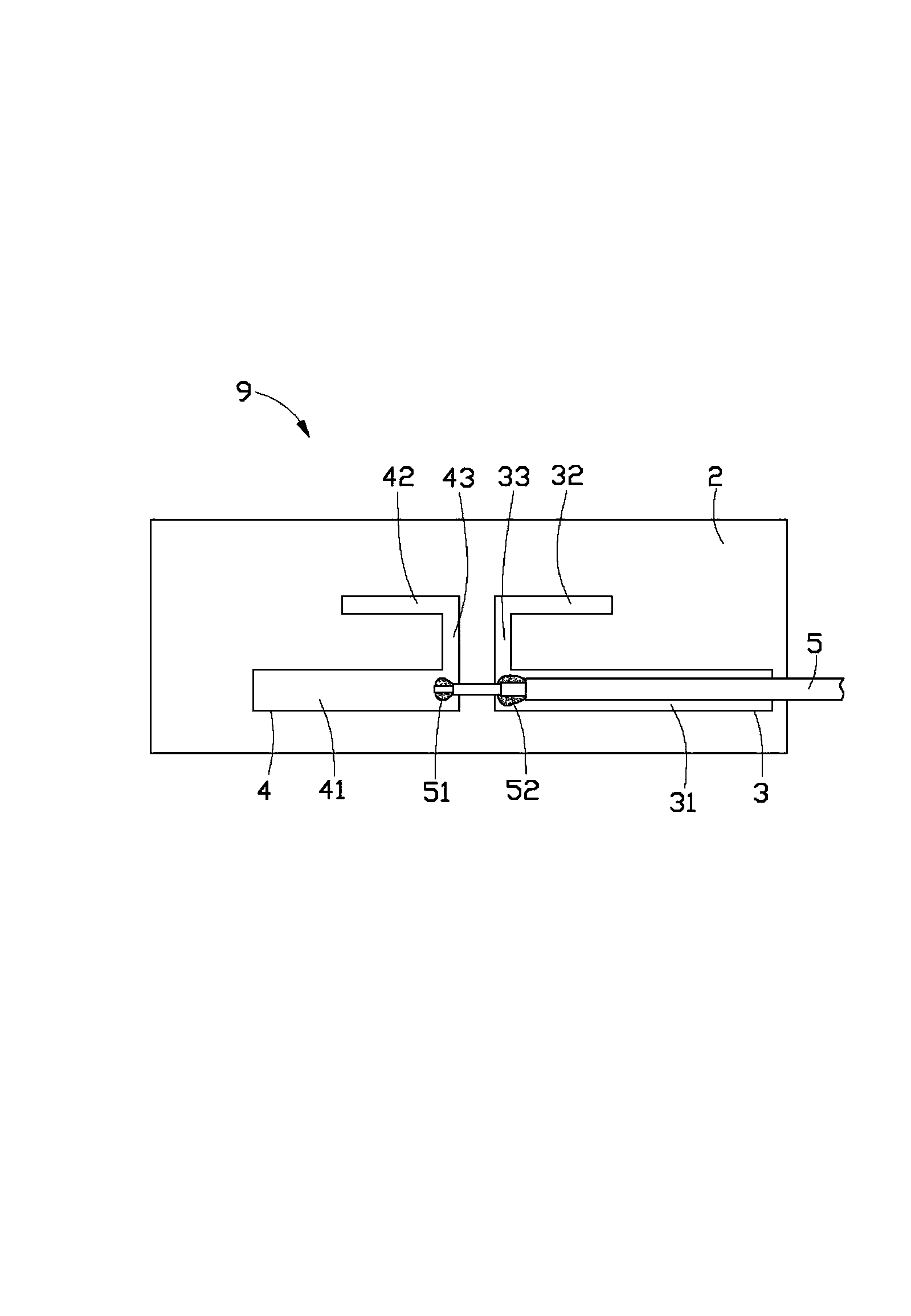
[0016] Please refer to figure 2 As shown, it is a plan view of the broadband antenna 1 of the first preferred embodiment. The broadband antenna 1 includes a printed circuit board 2 , a first antenna radiator 3 , a second antenna radiator 4 and a feeding device 5 . The first antenna radiator 3 and the second antenna radiator 4 are arranged on the surface of the printed circuit board 2. Specifically, the first antenna radiator 3 and the second antenna radiator 4 are the same printed circuit board 2 using conductive materials. surface. In other embodiments, the first antenna radiator 3 and the second antenna radiator 4 are located on different surfaces of the printed circuit board 2 .

[0017] The first antenna radiator 3 is roughly in an "n" shape, including a first middle section 33 and a first segment 31 and a second segment 32 respectively connected to the first middle section 33 . The lengths of the first segment 31 and the second segment 32 are not equal.

[0018] The s...


PUM


Abstract

The invention provides a broadband antenna which is installed in a wireless electronic device. The broadband antenna comprises a printed circuit board, a feeding device, a first antenna radiating body and a second antenna radiating body, wherein the first antenna radiating body and the second antenna radiating body are arranged on the surface of the printed circuit board. A gap is formed between the first antenna radiating body and the second antenna radiating body. The first antenna radiating body is of an n-shaped structure having the broadband function and comprises a first middle section, a first subsection and a second subsection, wherein the first subsection and the second subsection are connected with the first middle section, and the length of the first subsection is not equal to that of the second subsection. One end, close to the gap, of the first subsection and one end, close to the gap, of the second antenna radiating body are provided with a first feeding point and a second feeding point respectively. The feeding device is electrically connected with the first feeding point and the second feeding point and conducts feeding on the first antenna radiating body and the second antenna radiating body through the first feeding point and the second feeding point. One end, not electrically connected with the second feeding point, of the feeding device makes contact with a metal structure of the wireless electronic device so as to be grounded.

Description

technical field [0001] The invention relates to a broadband antenna. Background technique [0002] figure 1 It is a built-in antenna of a WiFi wireless device. The operating frequency used is the 5GHz frequency band. The antenna is based on the commonly used PIFA antenna. Among them, a1 is the main structure of the wireless radiator, a2 is the ground structure, a3 is the feed point (Feed), a4 is the ground point (shorting), a5 is the non-metallic holder, and b1 is the connection to the wireless transceiver unit RF coaxial line between the antenna. The working principle of this antenna is to generate a surface current in a1 through the high and low potential difference between a3 and a4. When the distribution of the surface current is just 1 / 4λ of the operating frequency, the antenna radiation effect will occur. Most of the built-in antennas used in current wireless products use the same concept, and the structure is nothing more than a grounding structure, and adding a gr...

Claims


Application Information

Patent Timeline
Patent Type & Authority Applications(China)
IPC IPC(8): H01Q1/38H01Q1/48H01Q1/50
Inventor 谢宗霖
Owner HONG FU JIN PRECISION IND (SHENZHEN) CO LTD
Why Eureka
Try Eureka