Leakage control device for ball valve telescopic joint of pump storage group

A technology for pumped storage units and leak-proof devices, which is applied to mechanical equipment, flange connections, passing components, etc., and can solve problems such as no obvious improvement, inability to fully open, and increased bolt tightening torque

Active Publication Date: 2013-12-04
STATE GRID CORP OF CHINA +2
View PDF6 Cites 1 Cited by
  • Summary
  • Abstract
  • Description
  • Claims
  • Application Information

AI Technical Summary

Problems solved by technology

Due to the different deformation of the horizontal U-shaped sealing ring, when the U-shaped mouth of the horizontal U-shaped sealing ring is opened, its expansion angle and size also change accordingly, and it cannot be fully opened or deformed, resulting in a large amount of water leakage, which cannot meet the requirements. Unit water pressure requirements
After various maintenance measures on site, such as replacing the seal of the expansion joint of the ball valve, readjusting the clearance fit of the movable ring, increasing the compression torque of the bolt, and applying sealant, etc., there is no obvious improvement

Method used


Image

  • Leakage control device for ball valve telescopic joint of pump storage group
  • Leakage control device for ball valve telescopic joint of pump storage group
  • Leakage control device for ball valve telescopic joint of pump storage group

Examples


Embodiment 1

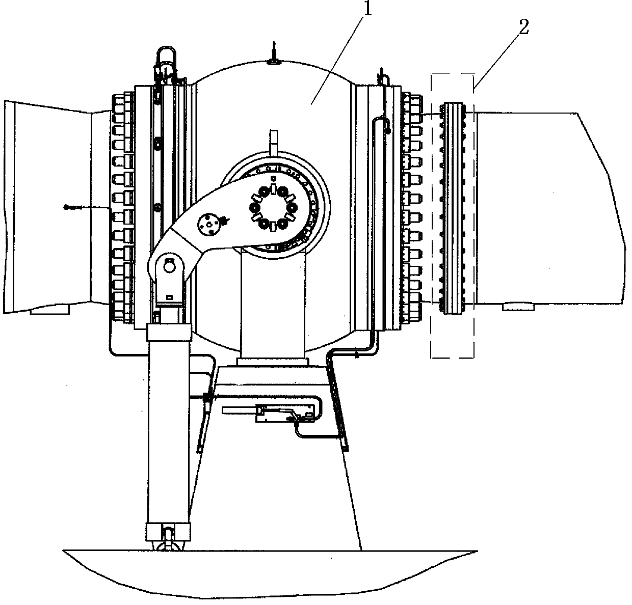
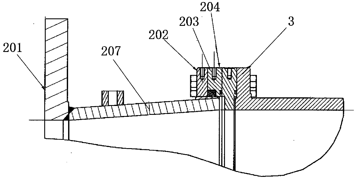
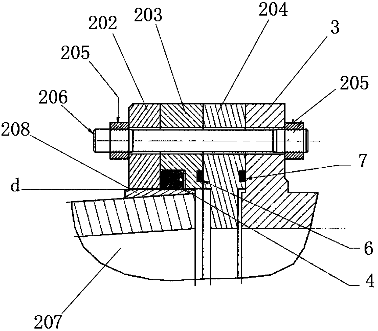
[0019] Embodiment 1: A leak-proof device for ball valve expansion joints of pumped storage units, see figure 1 , is an improvement made for the expansion joint downstream of the ball valve 1. The expansion joint 2 downstream of the ball valve is connected by the pipe flange 3 and the transition pipe 207 and a sealing structure is provided. Depend on figure 2 and image 3 It can be seen from the figure that the third movable ring 204, the second movable ring 203 and the first movable ring 202 are sequentially attached to the pipe flange 3, and the above four-layer structures are fixed through bolts 206, and nuts 205 are respectively installed at both ends of the bolts 206. Furthermore, an O-ring 8 is provided between the pipe flange 3 and the third movable ring 204 , and an O-ring 7 is provided between the third movable ring 204 and the second movable ring 203 . figure 2 and image 3 Among them, the transition pipe 207 is located inside the second movable ring 203 and the ...

Embodiment 2

[0021] Example 2: see Figure 5 , the content is basically the same as that of Example 1, and the similarities will not be repeated. The difference is that the combined O-shaped seal ring 5 is located at the notch of the horizontal U-shaped seal ring 4 open grooves, and the diameter of the combined O-shaped seal ring 5 is greater than The width of the opening groove of the horizontal U-shaped sealing ring 4. Under the action of water pressure, the combination O-shaped sealing ring 5 will be pressed into the opening groove of the horizontal U-shaped sealing ring 4, so as to keep the horizontal U-shaped sealing ring 4 from deformation. Thereby, the problem that the horizontal U-shaped sealing ring 4 cannot be tightly sealed due to the deformation caused by the weight of the expansion joint can be eliminated. Even if the horizontal U-shaped sealing ring 4 has deformation, the opening groove of the horizontal U-shaped sealing ring 4 cannot be tightly sealed with the equipment. Ho...


PUM


Abstract

The invention discloses a leakage control device for a ball valve telescopic joint of a pump storage group. A horizontal U-shaped seal ring is arranged in a ball valve downstream telescopic joint; the position of an open slot of the horizontal U-shaped seal ring is provided with a combined O-shaped seal ring; the combined O-shaped seal ring is separated into at least two sections; the at least two sections are connected by an instant adhesive; the thickness of the instant adhesive is smaller than the diameter of the combined O-shaped seal ring. According to the leakage control device for the ball valve telescopic joint of the pump storage group disclosed by the invention, the problem that the horizontal U-shaped seal ring deforms and cannot be tightly sealed due to the weight of the telescopic joint can be eliminated, and even if the horizontal U-shaped seal ring has deformation, the open slot of the horizontal U-shaped seal ring cannot be tightly sealed with equipment, but as the existence of the combined O-shaped seal ring, the horizontal U-shaped seal ring also can be tightly sealed with the equipment as well, and a gap cannot exist. Under the action of water pressure in a pipeline, an aqueous medium can flow through multiple sections of the combined O-shaped seal ring as well to enter the open slot of the horizontal U-shaped seal ring to expand the open slot of the horizontal U-shaped seal ring, and therefore, seal and water-stop effects are exerted.

Description

technical field [0001] The invention belongs to the technical field of pumped energy storage, and in particular relates to a leakage prevention device for a ball valve expansion joint of a pumped energy storage unit. Background technique [0002] Most of the pumped storage power stations are underground powerhouse structures, equipped with rated water head and rated power turbine working conditions, using water medium to pass through diversion tunnels, pressure steel pipes, ball valves, expansion joints downstream of ball valves, volutes, runners, draft pipes, etc. The circulation between the reservoir and the lower reservoir realizes the functions of power generation and water pumping. Therefore, in the entire water diversion channel system, the sealing of the water medium plays a vital role. If there is a large amount of water leakage in any point of equipment, it will cause water to flood the underground powerhouse, causing very serious consequences. Among them, the ball...

Claims


Application Information

Patent Timeline
Patent Type & Authority Applications(China)
IPC IPC(8): F16L23/16
Inventor 张旭秦鸿哲陈小冲贾先锋刘鹏龙王洋
Owner STATE GRID CORP OF CHINA
Why Eureka
Try Eureka