Long and steep downgrade energy dissipation deceleration road surface and construction process thereof

A road surface, energy dissipation technology, applied in the direction of roads, roads, special pavements, etc., can solve the problems of less obvious speed limit effect, large vehicle damage, poor durability, etc., achieve significant visual effects, prevent fatigue and numbness, and improve safety. sexual effect

Active Publication Date: 2013-12-04
WUHAN UNIV OF TECH
View PDF2 Cites 4 Cited by
  • Summary
  • Abstract
  • Description
  • Claims
  • Application Information

AI Technical Summary

Problems solved by technology

Thermoplastic vibration markings and rubber speed bumps are two commonly used deceleration facilities on expressways in my country. However, the force of thermoplastic vibration markings to force deceleration is not enough, and the speed limit effect on large trucks on expressways is not obvious; The speed has a certain control effect, but its durability is poor. It not only destroys the road surface during installation, but also causes great damage to the vehicle due to the fixing screws left after scrapping.

Method used


Image

  • Long and steep downgrade energy dissipation deceleration road surface and construction process thereof
  • Long and steep downgrade energy dissipation deceleration road surface and construction process thereof
  • Long and steep downgrade energy dissipation deceleration road surface and construction process thereof

Examples


Embodiment 1

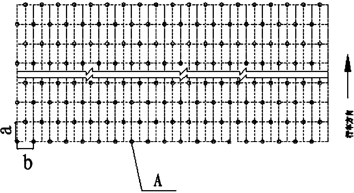
[0038] figure 1 The overall layout schematic diagram of the first embodiment provided by the present invention, by figure 1 It can be seen that the long-distance downhill energy dissipation deceleration pavement is composed of three thermoplastic protruding vibration markings perpendicular to the driving direction, the deceleration area I, and the deceleration area composed of three hump-type asphalt concrete base deceleration belts perpendicular to the driving direction. Ⅱ and deceleration area Ⅲ composed of two sections of asphalt concrete base deceleration spikes. Among them, the long downhill road surface refers to the downhill section with a continuous slope of more than 6 kilometers and an average longitudinal slope of more than 3%.

[0039] Among them, the interval L between deceleration zone I and deceleration zone II 1 10m, distance L between deceleration zone II and deceleration zone III 3 It is 20m. The thermoplastic protruding vibration markings are strip-shape...

Embodiment 2

[0046] The arrangement of embodiment 2 is basically the same as that of embodiment 1, the difference is that:

[0047] Distance L between deceleration zone Ⅰ and deceleration zone Ⅱ 1 is 12m, and the distance between deceleration zone II and deceleration zone III is L 3 It is 25m.

[0048] In the deceleration zone I, the longitudinal width L of each thermoplastic protruding vibration marking along the driving direction 5 is 400mm, the transverse width is the width of the road surface, the height h of the protruding block 1 in each thermoplastic protruding vibrating marking line is 6mm, and the distance L between two adjacent thermoplastic protruding vibrating marking lines 0 It is 8m.

[0049] In deceleration area II, from the direction of driving, the first hump-type asphalt concrete base deceleration belt has a height H 1 20mm, width W 1 50mm, the height of the second hump-type asphalt speed bump is H 2 40mm, width W 2 80mm, the height of the third hump-type asphalt s...

Embodiment 3

[0053] The long-distance downhill energy-dissipating deceleration pavement provided in Example 3 consists of deceleration zone I composed of three thermoplastic protrusion-type vibration markings perpendicular to the driving direction, and two hump-type asphalt concrete-based deceleration belts perpendicular to the driving direction. The deceleration zone Ⅱ formed by the deceleration zone Ⅱ and the deceleration zone Ⅲ formed by a section of asphalt concrete base deceleration spikes.

[0054] Among them, the interval L between deceleration zone I and deceleration zone II 1 10m, distance L between deceleration zone II and deceleration zone III 3 is 10m.

[0055] Among them, in the deceleration area I, the thermoplastic protruding vibration markings are strip-shaped, and the longitudinal width of each thermoplastic protruding vibration marking along the driving direction is L 5 is 600 (300) mm, the transverse width is the width of the road surface, the height h of the protrudin...


PUM


Abstract

The invention discloses a long and steep downgrade energy dissipation deceleration road surface and a construction process thereof. A deceleration region I formed by three thermoplastic protruding vibratile mark lines perpendicular to the traveling direction, a deceleration region II formed by 1-3 hump-type bitumen concrete base deceleration bands perpendicular to the traveling direction and a deceleration region III formed by 1-2 sections of deceleration road studs are arranged in the traveling direction of the energy dissipation deceleration road surface in sequence. The construction process of the long and steep downgrade energy dissipation deceleration road surface mainly comprises the steps of road surface pretreatment, mounting road section drawn line, mounting and maintaining deceleration facilities and the like. According to the invention, the deceleration region I mainly plays a role of reminding a driver to decelerate; the deceleration regions II and III mainly play a role of forcibly decelerating, and meanwhile can eliminate the driver's vision fatigue and torpor, as a result, the driver is prevented from immediately accelerating after just deceleration, the purpose of long-distance speed control is realized, the deceleration road surface does not damage vehicles, acceleration facilities are durable, the construction process is simple, and the cost is low.

Description

technical field [0001] The invention belongs to the technical field of traffic facilities, and provides a long downhill energy-dissipating and decelerating pavement and a construction process thereof. Background technique [0002] With the rapid development of the transportation industry, the level of highway construction in our country has been continuously improved, and the quality of highway pavement is getting better and better, so the speed of driving on the highway is getting faster and faster, but there are more and more traffic accidents. Especially for expressways in mountainous areas, due to the limitation of their own geographical conditions, many complicated driving routes have been produced in the process of expressway construction, and the complexity of mountain climate has brought huge hidden dangers to expressway driving safety. Mountainous highways often contain long slopes and continuous downhill sections. Due to excessive speed and brake failure caused by ...

Claims


Application Information

Patent Timeline
Patent Type & Authority Applications(China)
IPC IPC(8): E01C9/00E01F9/08E01F9/047E01F9/06E01F9/553
Inventor 李相国何超褚端峰张存保熊建文谭洪波
Owner WUHAN UNIV OF TECH
Why Eureka
Try Eureka