
Full-automatic oil-chromatography sample feeding device for transformer and operation method

A technology of transformer oil and sampling device, applied in measuring devices, instruments, scientific instruments, etc., can solve the problems of cumbersome steps, inability to use together, and rapid consumption of standard gas, so as to improve detection efficiency, avoid volume errors, and save manpower Effect

Active Publication Date: 2013-11-27
ELECTRIC POWER SCI RES INST OF GUIZHOU POWER GRID CO LTD +1
View PDF6 Cites 6 Cited by
  • Summary
  • Abstract
  • Description
  • Claims
  • Application Information

AI Technical Summary

Problems solved by technology

[0003] However, the current oil chromatography detection in the laboratory has many manual steps, the steps are cumbersome, and the detection requirements for the operator are high, and the operator must stick to it in the laboratory throughout the process.
Although the oil chromatography online monitoring technology can realize automatic sampling, it is limited to one oil sample and cannot realize the detection of multiple oil samples. In order to realize automatic sampling, it must be used in conjunction with the software developed by it, and it cannot be used with existing ones. It is used together with the laboratory oil chromatography detection software
Although portable oil chromatography can be detected on site, its operation process and steps are completely similar to those of laboratory oil chromatography detection, and the standard gas carried is consumed quickly, which is not conducive to the detection of multiple oil samples

Method used


Image

  • Full-automatic oil-chromatography sample feeding device for transformer and operation method
  • Full-automatic oil-chromatography sample feeding device for transformer and operation method

Examples


Embodiment 1

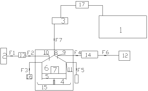
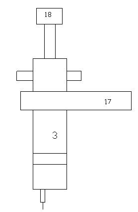
[0030] Example 1 figure 1 with figure 2 As shown, the oil-gas separation device includes a degassing tank 6 with a movable bottom 5, a bottom pushing device 3 and a gravity compensation device 4 are connected to the bottom 6, and a stirring device 7 is provided in the degassing tank 6. The stirring device 7 is a magnetic stirrer. The degassing tank 6 is located in the constant temperature box 15. The degassing tank 6 is provided with a gas inlet 8, a sampling port 9, a nitrogen gas inlet 10 and an oil discharge port 11. The gas device 3 is connected, and an oil-proof valve F7 is provided between the gas inlet 8 and the gas collecting device 3; the sampling port 9 is connected to the sample 12, and the liquid quantitative sampler 14 is connected between the sampling port 9 and the sample 12; The pipeline between the port 9 and the liquid quantitative sampler 14 is connected with a degassing tank inlet valve F4, and the pipeline between the sample 12 and the liquid quantitative ...


PUM


Abstract

The invention discloses a full-automatic oil-chromatography sample feeding device for a transformer. The device comprises a detection device, an oil-gas separation device, a gas tank, a gas collection device and an inspection device, wherein the oil-gas separation device comprises a degassing tank with movable bottom; a tank bottom pushing device and a gravity compensation device are connected to the tank bottom; a stirring device is arranged in the degassing tank; a gas sampling hole, a sampling hole, a nitrogen inlet and an oil discharging hole are formed in the degassing tank, the gas sampling hole is connected with the gas collection device, the sampling hole is connected with a sample, the nitrogen inlet is connected with the gas tank, and the oil discharging hole is connected with an oil collection tank. The full-automatic oil-chromatography sample feeding device aims at pretreatment processes of detecting gas components dissolved in transformer oil in a gas chromatography manner in a laboratory; the device automation is realized in operation processes originally required to be manually operated, so that the detection efficiency of an oil-immersed transformer can be improved, errors brought from pretreatment links can be reduced, the manpower can be saved, and the device is worthy of being popularized and applied.

Description

Technical field [0001] The invention relates to a full-automatic sampling device and operation method for transformer oil chromatogram, and belongs to the technical field of power grid equipment detection. Background technique [0002] At present, in the fault diagnosis of oil-immersed transformers, chromatographic analysis is commonly used to analyze the dissolved gas in the oil in order to find the problems in the transformer as soon as possible and take countermeasures. This is an important means to supervise and ensure the safe operation of the transformer. Of course, some oil-filled current transformers or voltage transformers and bushings can also be used to detect latent faults by detecting gas components in the oil. Various transformer oil chromatographic detection schemes are emerging in endlessly. The main detection for main transformer oil Technologies include laboratory oil chromatography detection, online oil chromatography detection and portable oil chromatography d...

Claims


Application Information

Patent Timeline
Patent Type & Authority Applications(China)
IPC IPC(8): G01N30/20
Inventor 张英潘云陈荣余鹏程李军卫张凤如蒋震
Owner ELECTRIC POWER SCI RES INST OF GUIZHOU POWER GRID CO LTD
Learn More