
Winding machine

A technology of winding machine and winding wheel, which is applied in the direction of conveying filamentous materials, thin material processing, transportation and packaging, etc. It can solve the problems of messy arrangement, large space occupation and irregularity on the winding machine

Inactive Publication Date: 2013-11-27
象山科迪液压机械制造有限公司
View PDF7 Cites 5 Cited by
  • Summary
  • Abstract
  • Description
  • Claims
  • Application Information

AI Technical Summary

Problems solved by technology

[0002] With the shortage of human resources and the widespread use of plastic equipment, the application requirements for the use of winders are getting higher and higher. In the prior art, both the cycloid and the winding wheel are driven by the main motor, so the speed of the cycloid cannot be adjusted. The winding machine is only suitable for winding pipes of one specification. If the pipes of different specifications are wound, the arrangement of the pipes will be messy, irregular, occupy a large space, and waste manual collection time.
[0003] Please refer to the CN201447237U Chinese patent published on May 5, 2010 for the prior art, which discloses a winding machine. Since this winding machine is not provided with a cycloid that moves in the lateral direction, the pipe rolls until it is closed. The sub-arrangement on the winding machine is messy, irregular, and takes up a lot of space

Method used


Image

  • Winding machine
  • Winding machine
  • Winding machine

Examples


Embodiment Construction

[0033] The present invention will be further described below in conjunction with the accompanying drawings and embodiments.

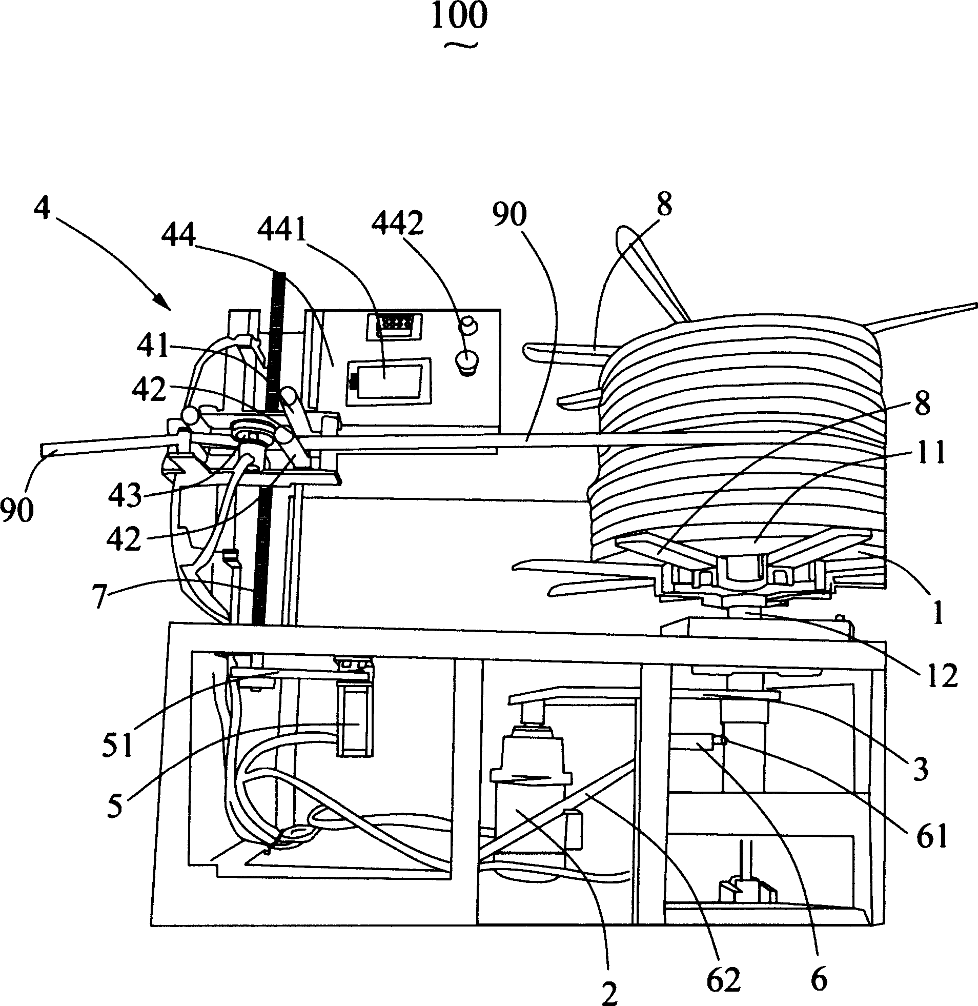
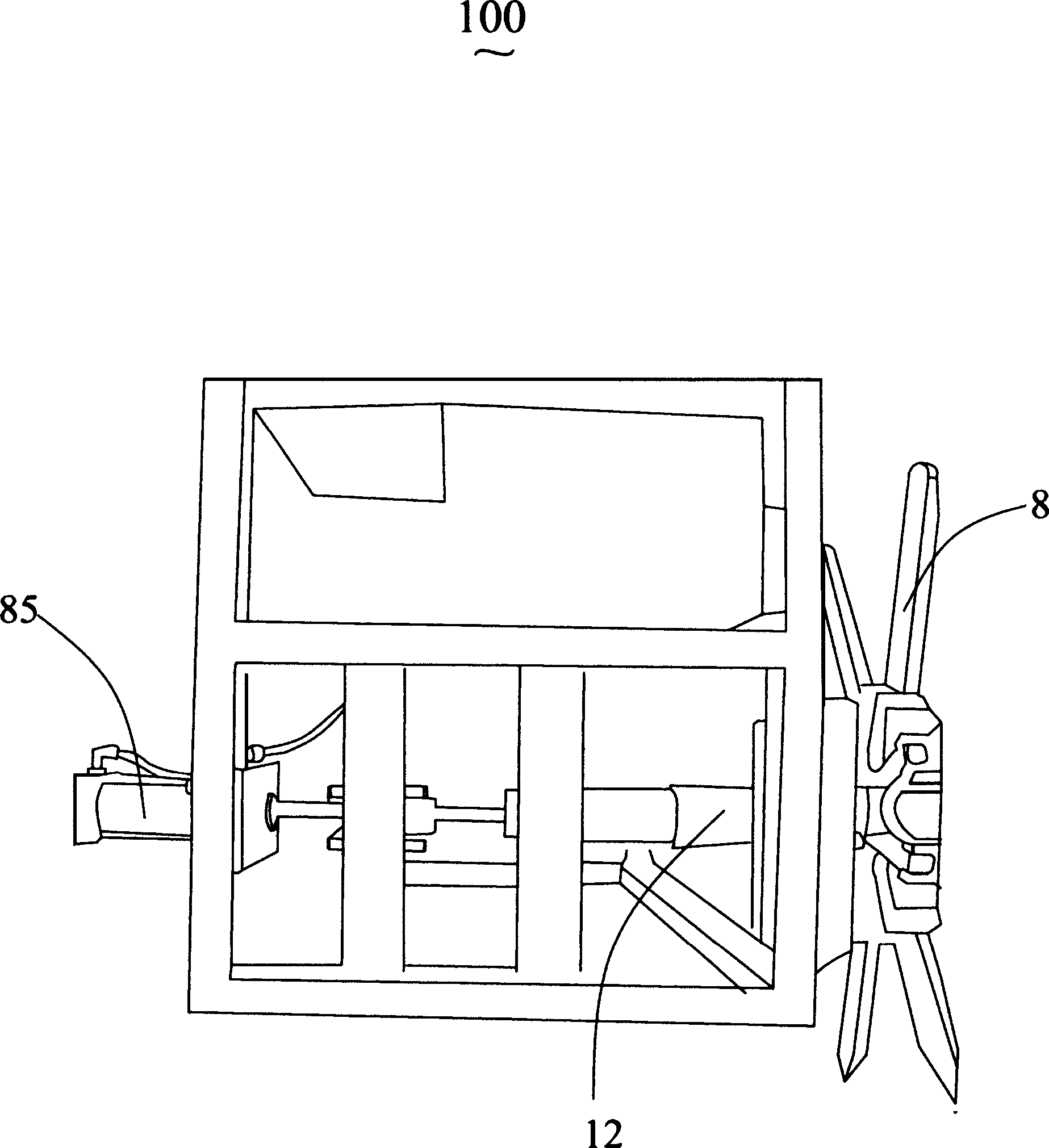
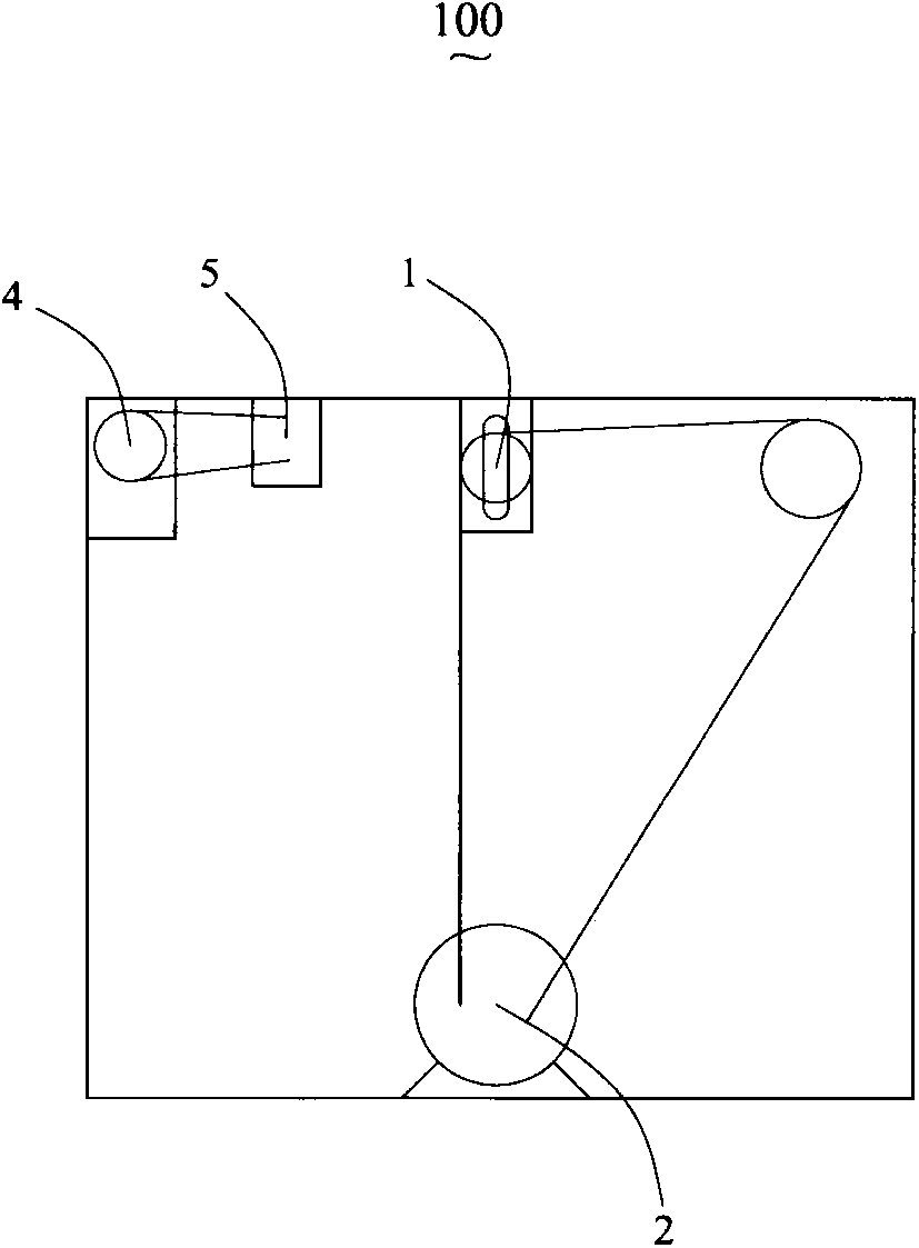
[0034] like Figure 1 to Figure 3 Shown is a winder 100 in accordance with the present invention for winding a tube 90 such as a hose.

[0035] The winder 100 includes: a winder 1 , a main motor 2 for driving the winder 1 to rotate, and a chain 3 drivingly connected between the main motor 2 and the winder 1 . The take-up wheel 1 has a reel 11 for winding the tube 90 and a take-up shaft 12 at least partially arranged in the reel 11. The main motor 2 drives the take-up shaft 12 to rotate through the chain 3 and then drives the reel 11 to rotate along the axis line. The rotation of the drum 11 along the axis is used to automatically wind the tube 90 onto the drum 11 . The winder 100 is further provided with a cycloid 4, a drive motor 5 for driving the cycloid 4 to move laterally, and a sensor probe 6 for detecting the rotation of the winding wheel 1. Th...


PUM


Abstract

The invention discloses a winding machine which comprises a winding wheel, a main motor driving the winding wheel to rotate and a chain connected between the main motor and the winding wheel in a transmission mode. The winding wheel is provided with a reel for a pipe to wind on and a winding shaft at least partially arranged in the reel, the main motor drives the winding shaft to rotate through the chain to further drive the reel to rotate along the axis, and the reel rotates along the axis to automatically wind the pipe on the reel. The winding machine further comprises a cycloid device, a driving motor driving the cycloid device to move transversely and a sensor probe used for detecting rotating of the winding wheel. The cycloid device is used for neatly winding the pipe on the winding wheel. By means of the winding machine, the pipe can be neatly wound on the winding wheel.

Description

technical field [0001] The invention relates to a winder, in particular to a winder for winding a hose. Background technique [0002] With the shortage of human resources and the widespread use of plastic equipment, the application requirements for the use of winders are getting higher and higher. In the prior art, both the cycloid and the winding wheel are driven by the main motor, so the speed of the cycloid cannot be adjusted. The winder is only suitable for one type of tube winding. If different specifications are wound, the tubes will be arranged in a mess, not neatly arranged, take up a lot of space, and waste manual processing time. [0003] For the prior art, please refer to the Chinese Patent No. CN201447237U published on May 5, 2010, which discloses a winder. Since this winder is not provided with a cycloid that moves in the lateral direction, the pipe is rolled up to the winder. The coiling machine is arranged in a messy and untidy manner and takes up a lot of sp...

Claims


Application Information

Patent Timeline
Patent Type & Authority Applications(China)
IPC IPC(8): B65H54/28B65H54/70
Inventor 杨志刚
Owner 象山科迪液压机械制造有限公司
Learn More