
Power-on reset circuit

An electrical reset and circuit technology, applied in electrical components, electronic switches, pulse technology, etc., can solve the problems of high power consumption of POR circuits, and achieve the effects of small current, reduced area, and reduced circuit power consumption

Active Publication Date: 2013-11-20
SHANGHAI INTEGRATED CIRCUIT RES & DEV CENT
View PDF6 Cites 9 Cited by
  • Summary
  • Abstract
  • Description
  • Claims
  • Application Information

AI Technical Summary

Problems solved by technology

In order to meet these requirements, the traditional POR circuit will consume a large power consumption, which is undesirable in an integrated system

Method used


Image

  • Power-on reset circuit
  • Power-on reset circuit
  • Power-on reset circuit

Examples


Embodiment Construction

[0016] In order to make the content of the present invention clearer and easier to understand, the content of the present invention will be further described below in conjunction with the accompanying drawings. Of course, the present invention is not limited to this specific embodiment, and general replacements known to those skilled in the art are also covered within the protection scope of the present invention.

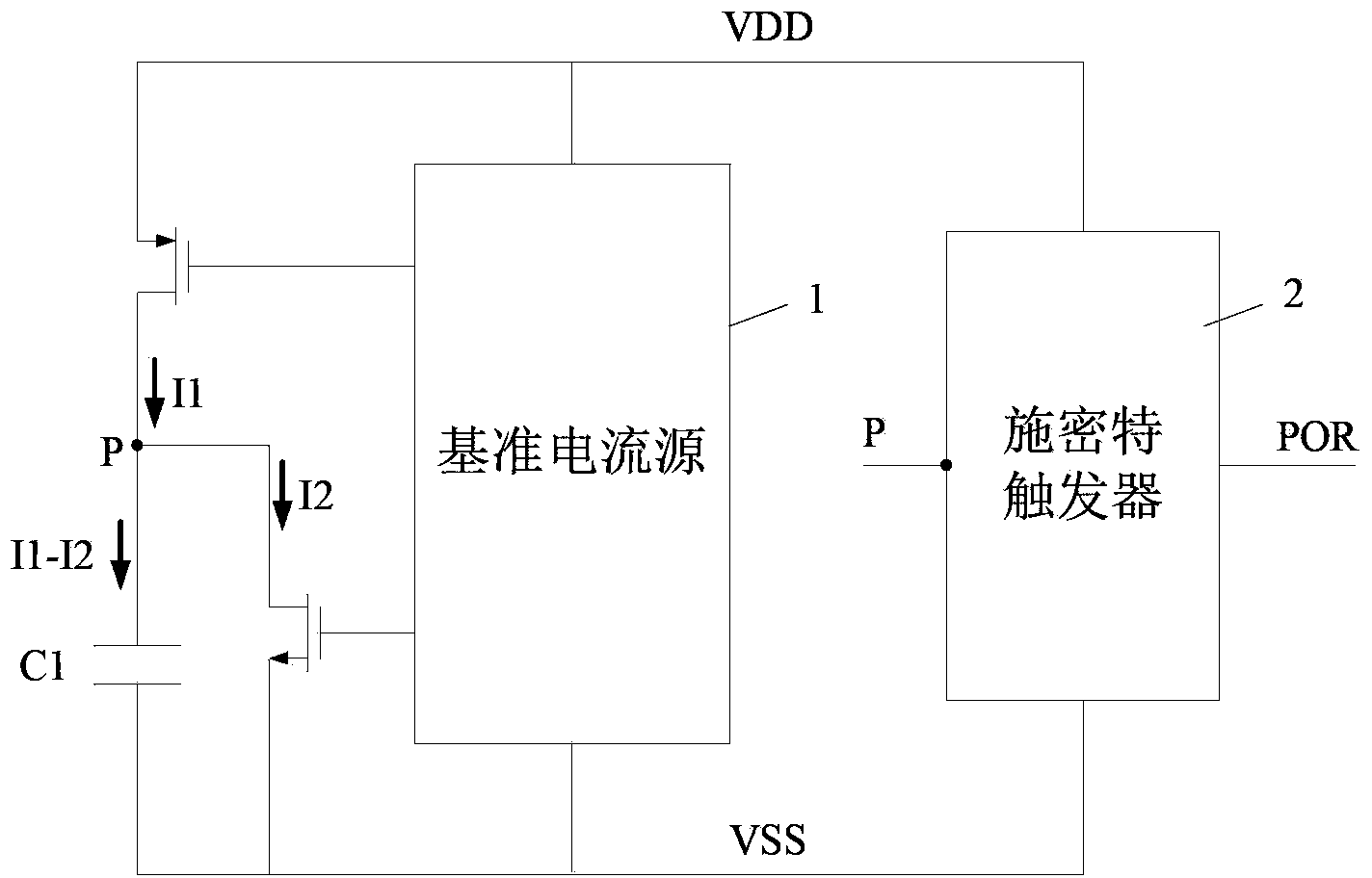
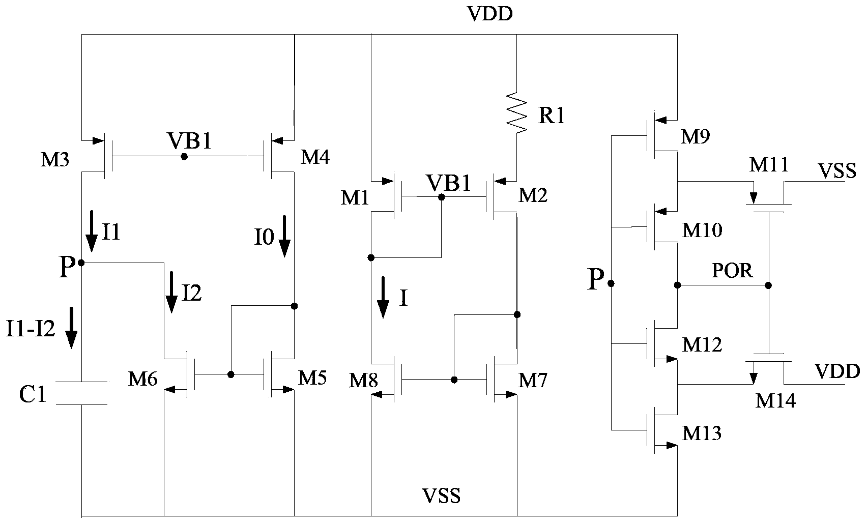
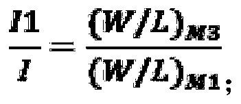
[0017] see figure 1 , figure 1 It is a structural schematic diagram of the power-on reset circuit of the present invention. The power-on reset circuit includes a voltage source VDD, a reference current source 1 , a Schmitt trigger (Schmitt trigger) 2 , a capacitor C1 , a first current mirror circuit and a second current mirror circuit. The reference current source 1 is connected with the voltage source VDD for providing the reference current I, the first current mirror circuit copies the reference current I proportional relationship as the first current I1, and t...


PUM


Abstract

The invention discloses a power-on reset circuit, which comprises a voltage source, a capacitor, a Schmidt trigger, a reference current source, a first current mirror circuit and a second current mirror circuit, wherein one end of the capacitor is connected with the input end of the Schmidt trigger, and the other end of the capacitor is grounded; the reference current source is connected with the voltage source; the first current mirror circuit is used for duplicating the reference current of the reference current source into first current in proportional relation way; the second current mirror circuit is used for duplicating the reference source of the reference current source into second current in a proportional relation way; and an output impeder of the second current mirror circuit is connected in parallel with the capacitor, and is connected in series with the output end of the first current mirror circuit. Due to the adoption of the power-on reset circuit disclosed by the invention, low power consumption and small area can be realized, and wide reset pulse bands can be generated in a large power-on speed range.

Description

technical field [0001] The invention relates to the field of integrated circuits, in particular to a power-on reset circuit. Background technique [0002] An important feature of the current chip development is miniaturization and integration. With the development of the mobile and portable market, people's requirements for chips are not only satisfied with the realization of functions, but also the cost, integration, power consumption, etc. of chips. There are increasingly higher demands. The single-chip system integrated chip solution brought by the system chip can not only significantly increase the integration level, reduce the chip volume, and increase the packaging density, but also can effectively reduce the cost and cost of the chip system. At the same time, the chip system also puts forward higher requirements on the performance, area, function, stability and other indicators of each part of the module. [0003] The power-on reset (POR) circuit is widely used, and...

Claims


Application Information

Patent Timeline
Patent Type & Authority Applications(China)
IPC IPC(8): H03K17/22
Inventor 何学红董林妹孙翔
Owner SHANGHAI INTEGRATED CIRCUIT RES & DEV CENT
Learn More