Multifunctional intelligent device for compensating reactive power and adjusting active power
A technology for compensating reactive power and compensating devices, which is applied in the field of compensating three-phase power unbalance and reactive power compensation, and surge-free switching of reactive power compensation devices, which can solve the problems of low capacitor utilization, high cost, and inability to compensate reactive power. Balance active power and other issues to achieve the effects of strong practicability, improved life, and improved response speed
- Summary
- Abstract
- Description
- Claims
- Application Information
AI Technical Summary
Problems solved by technology
Method used
Image
Examples
Embodiment 1
[0036] Figure 6 It is the schematic diagram of each phase current compensation device without detection and compensation devices in the star connection: it includes a shell and a micro-break, three-phase current from the power system, six voltage sampling circuits, and a power controller. , a circuit breaker ZK, and a Y compensation unit. In this example, the compensation device in the compensation unit is a capacitor. Generally, the switches J1, J2, J3 and J0 are synchronous switches with contacts, but when putting in reactive devices, first In the case of closing J0 and cutting J0 back when removing reactive components, it can use an ordinary switch. The three-phase current from the power system generally comes from the three transformers that detect the three-phase current load in the power distribution panel power receiving cabinet, which can be an analog signal of 0--5A or a digital signal from the network . When it is an analog signal, it is connected to the analog in...
Embodiment 2
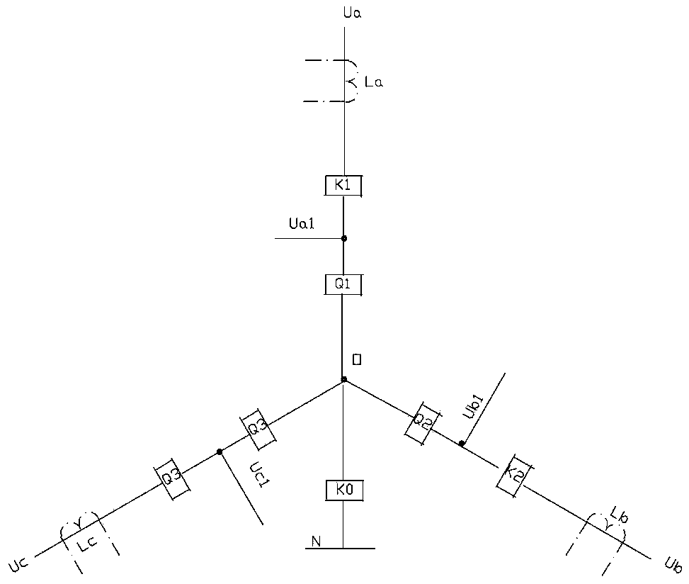
[0038] Figure 7 It is the schematic diagram of each phase current compensation device with detection and compensation devices in star connection: this embodiment is in Figure 5 The current circuit for detecting the three-phase compensation circuit is added on the basis of the above, and the current sampling is composed of three transformers La, Lb, and Lc used to detect the three-phase current load, and one end of them is respectively connected to the power controller The analog input ends of AI4, AI5, and AI6 are connected together, and then connected to the COM terminal of the power controller. Due to the detection of the three-phase current inside the reactive components, the power controller can calculate according to the detected current value and the switching status of the reactive components, the parameters of the reactive components and the grid voltage at different working times of the device. The current value of normal work, the calculated current is compared wi...
Embodiment 3
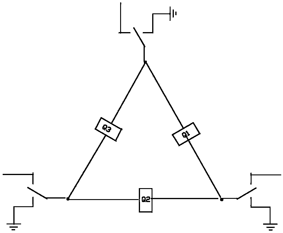
[0040] Figure 8It is the schematic diagram of the compensation device that does not detect the internal phase current of the compensation device and has no discharge circuit in the angle connection method: it includes a shell and a micro-break, three-phase current from the power system, and six voltage sampling circuits are installed in the shell. , a power controller, a circuit breaker ZK, a △ compensation unit composed of three single-phase capacitors, in this example the compensation device in the compensation unit is a capacitor, here switches J1, J3, J5 and J2, J4, J6 They are synchronous switches with contacts. When the switches J1, J3, and J5 are switched on and then disconnected, they can use ordinary switches, such as OMRON's MG2. The three-phase current from the power system generally comes from the three current transformers that detect the three-phase current load in the power distribution panel power receiving cabinet. It can be an analog signal of 0--5A or a dig...
PUM
 Abstract
Description
Claims
Application Information
 - R&D
- Intellectual Property
- Life Sciences
- Materials
- Tech Scout
- Unparalleled Data Quality
- Higher Quality Content
- 60% Fewer Hallucinations
Browse by: Latest US Patents, China's latest patents, Technical Efficacy Thesaurus, Application Domain, Technology Topic, Popular Technical Reports.
© 2025 PatSnap. All rights reserved.Legal|Privacy policy|Modern Slavery Act Transparency Statement|Sitemap|About US| Contact US: help@patsnap.com


