Large-scale split installation mouse cage type bearing framework
A squirrel cage type and frame technology is applied in the field of large-scale split-installed squirrel cage type load-bearing frames, which can solve the problems of coaxial error of the upper mounting plate, difficulty in ensuring the level of the mounting plate, etc. Adjustability, uniform effect of thermal deformation characteristics
- Summary
- Abstract
- Description
- Claims
- Application Information
AI Technical Summary
Problems solved by technology
Method used
Image

Examples
specific Embodiment approach 1
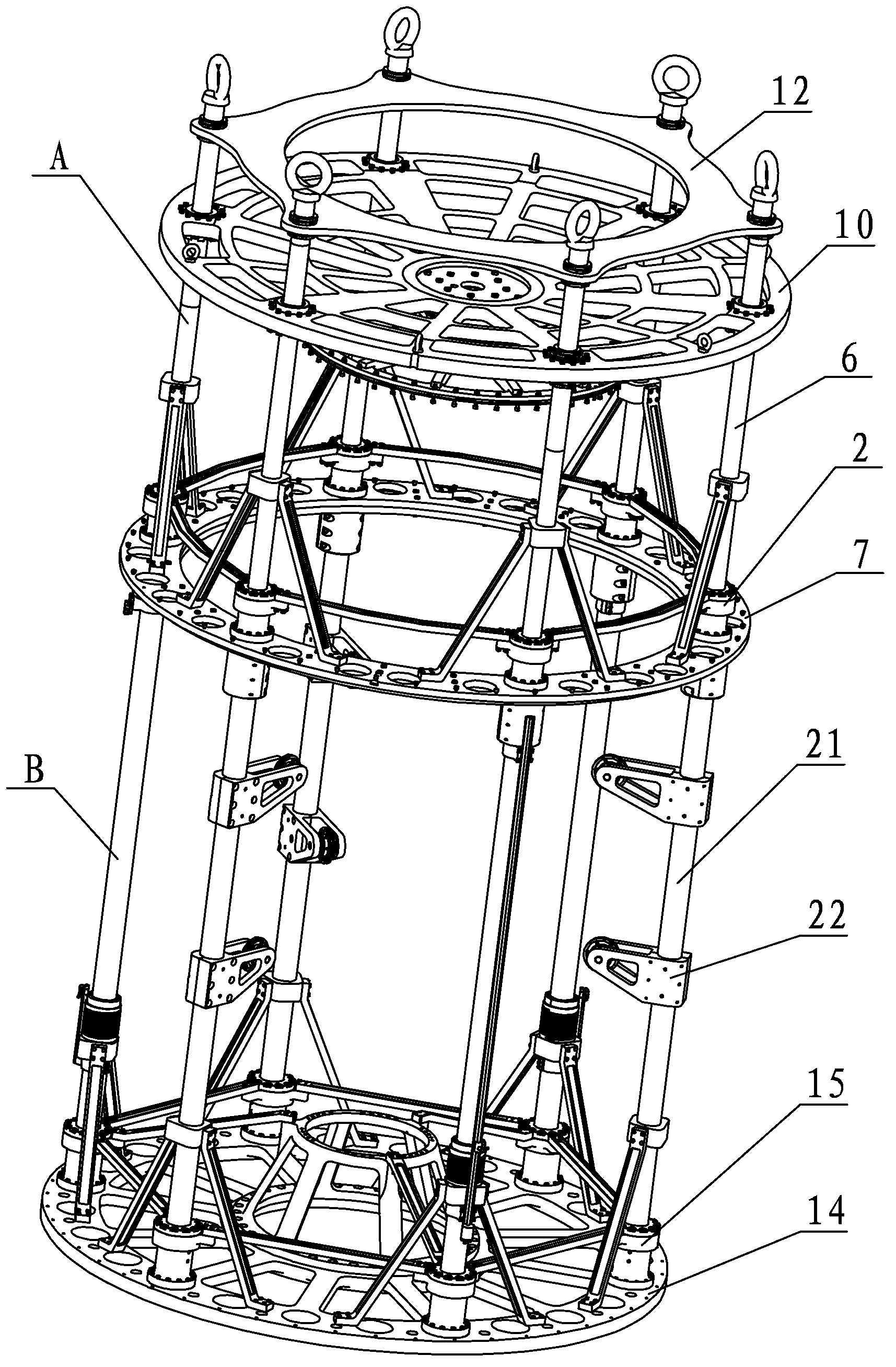
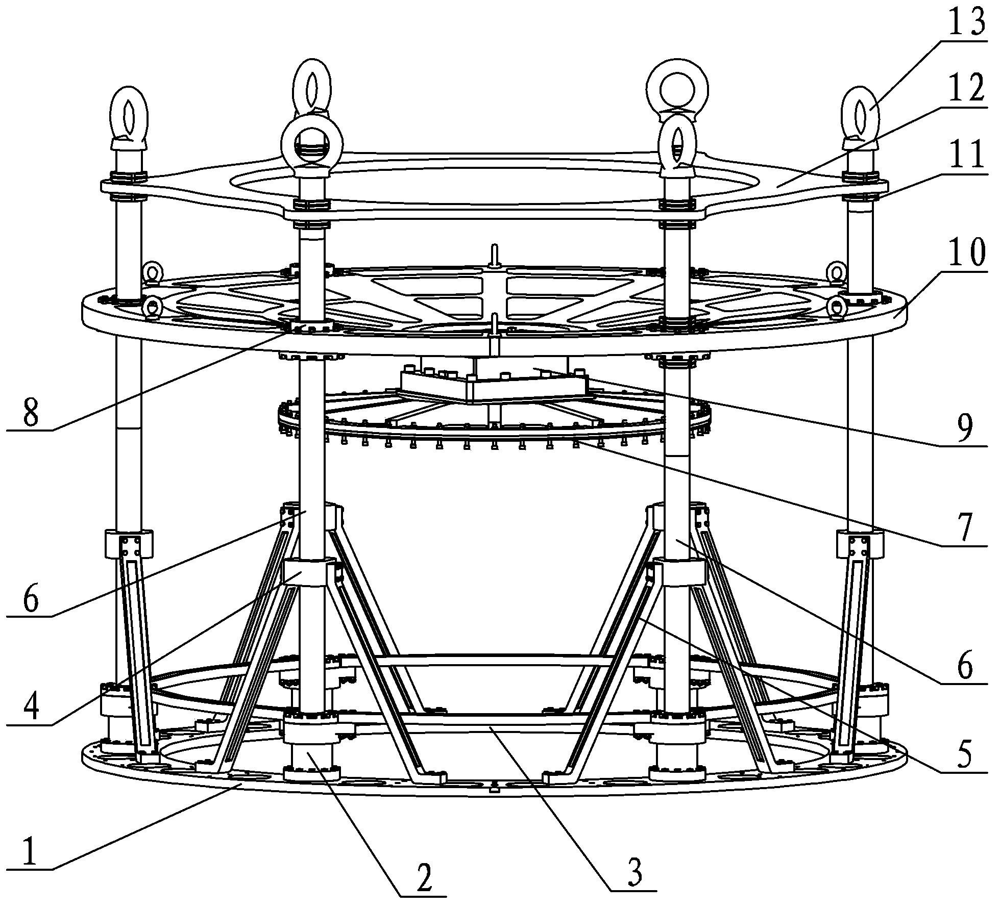
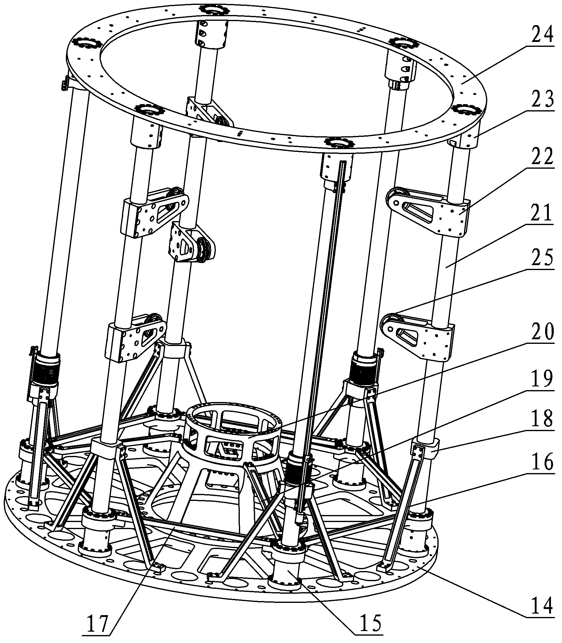
[0013] Specific implementation mode one: combine Figure 1 ~ Figure 3 Describe this embodiment. This embodiment includes an upper load-bearing frame A and a lower load-bearing frame B. The upper load-bearing frame A includes a first base 1, a mechanical component mounting plate 7, a six-dimensional force sensor 9, a mounting substrate 10, and a load-bearing frame. Plate 12, six first support rod bases 2, six first base reinforcement ribs 3, six upper frame support rods 6, six guide seats 8, six eyebolt screws 13 and multiple lock nuts 11, bearing force The plate 12, the installation base plate 10 and the first base 1 are arranged parallel and coaxially from top to bottom. Six first support rod bases 2 are evenly distributed along the edge of the upper end surface of the first base 1. The first base 1 is connected by a connecting element, and a first base reinforcement rib 3 is arranged between every two adjacent first support rod bases 2, and six first base reinforcement ribs ...
specific Embodiment approach 2
[0017] Specific implementation mode two: combination figure 2 Describe this embodiment, the difference between this embodiment and specific embodiment 1 is that the upper load-bearing frame A also includes six upper frame oblique rib slides 4 and twelve upper frame support rod oblique ribs 5, each upper frame An upper frame oblique reinforcing rib slide seat 4 is installed on the support bar 6, and the upper frame oblique reinforcing rib sliding seat 4 is located between the installation base plate 10 and the first support rod base 2, and each upper frame oblique reinforcing rib sliding seat 4 is equipped with Two upper frame support rod oblique reinforcement ribs 5, the two upper frame support rod oblique reinforcement ribs 5 are symmetrically arranged on both sides of the upper frame oblique reinforcement rib slide seat 4, and the upper end of each upper frame support rod oblique reinforcement rib 5 The connecting element is connected with the upper frame oblique rib slide ...
specific Embodiment approach 3
[0018] Specific implementation mode three: combination figure 2 Describe this embodiment, among the six guide seats 8 in this embodiment, three of them are linear bearings, and the other three are nut assemblies, and the three linear bearings and three nut assemblies are intersected. Frame support rods 6 are threaded. The linear bearing enables the installation substrate 10 to eliminate the coaxial error during the adjustment process, so that the horizontal position of the installation substrate 10 is accurate, and the function of the nut assembly is to provide accurate position adjustment for the installation substrate 10 . Other compositions and connections are the same as those in Embodiment 1 or 2.
PUM
 Abstract
Description
Claims
Application Information
 - R&D
- Intellectual Property
- Life Sciences
- Materials
- Tech Scout
- Unparalleled Data Quality
- Higher Quality Content
- 60% Fewer Hallucinations
Browse by: Latest US Patents, China's latest patents, Technical Efficacy Thesaurus, Application Domain, Technology Topic, Popular Technical Reports.
© 2025 PatSnap. All rights reserved.Legal|Privacy policy|Modern Slavery Act Transparency Statement|Sitemap|About US| Contact US: help@patsnap.com