Ultrasonic-assisted vacuum brazing equipment
An ultrasonic and vacuum technology, applied in welding equipment, metal processing equipment, manufacturing tools, etc., can solve the problems of poor interface bonding performance, exposure, unstable joint quality, etc., achieve high connection strength, prevent secondary pollution and oxidation, The effect of improved welding quality
Active Publication Date: 2013-11-20
HARBIN INST OF TECH AT WEIHAI
View PDF8 Cites 38 Cited by
- Summary
- Abstract
- Description
- Claims
- Application Information
AI Technical Summary
Problems solved by technology
[0004] The purpose of the present invention is to solve the problem that the existing ultrasonic assisted brazing equipment is exposed to the air when the workpiece and the brazing material are to be welded, and the weldment and the
Method used
View moreImage
Smart ImageViewing Examples
Examples
 PUM
 Abstract
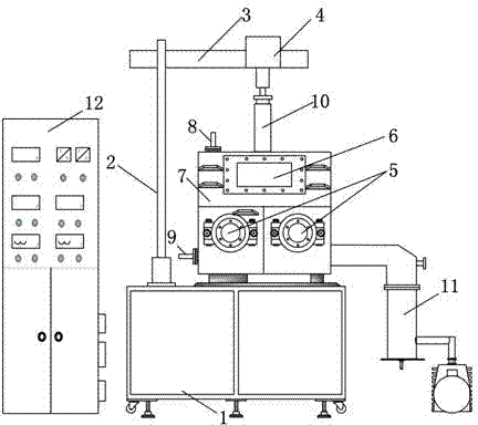
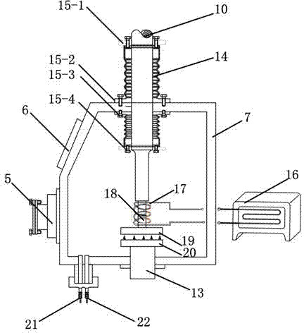
The invention discloses ultrasonic-assisted vacuum brazing equipment. The ultrasonic-assisted vacuum brazing equipment is characterized in that a vacuum chamber is arranged on a rack, and a screw rod guide rail upright is arranged on the rack on one side of the vacuum chamber. A cross beam is arranged at the upper end of the screw rod guide rail upright. An ultrasonic transducer is fixed on the cross beam. An ultrasonic amplitude transforming rod extends into the vacuum chamber through a flange. A mounting workbench and a heating plate are arranged below the ultrasonic amplitude transforming rod in the vacuum chamber. A lifting device on the rack penetrates the vacuum chamber to be connected with the heating plate. An induction heating coil is arranged between the mounting workbench and the ultrasonic amplitude transforming rod, and is connected with an induction heating device outside the vacuum chamber. An air inlet, an air exhaust port, two vacuum glove ports, a vacuum observation port, a vacuum gauge port, a thermocouple port, the ultrasonic transducer, the heating plate, the induction heating device, a vacuum gauge, a thermocouple and a vacuum pump are arranged on the wall of the vacuum chamber, and connected with a control cabinet through signal wires. Ultrasonic-assisted brazing in vacuum or protective atmosphere is realized.
Description
technical field [0001] The invention relates to brazing equipment, in particular to an ultrasonic-assisted vacuum brazing equipment with high joint strength and good quality after welding. Background technique [0002] As we all know, as an important material connection technology, brazing plays a vital role in the development of modern industrial technology. It can not only realize the connection of metal materials, but also realize the connection of new materials such as ceramics and composite materials. Especially for the connection of dissimilar materials, brazing has advantages that other welding methods cannot match. However, for the brazing connection of materials, the removal of the oxide film on the surface of the material to be welded has an important influence on the wetting and spreading of the solder and the interaction between the solder and the base metal. Decisive factor for obtaining high performance brazed joints. Ultrasonic-assisted brazing technology us...
Claims
Login to View More Application Information
Patent Timeline
 IPC IPC(8): B23K3/00B23K1/06B23K1/008B23K1/20B23K1/002
Inventor 宋晓国周利王斌刘多冯吉才
Owner HARBIN INST OF TECH AT WEIHAI
Features
- R&D
- Intellectual Property
- Life Sciences
- Materials
- Tech Scout
- Unparalleled Data Quality
- Higher Quality Content
- 60% Fewer Hallucinations
Learn More Browse by: Latest US Patents, China's latest patents, Technical Efficacy Thesaurus, Application Domain, Technology Topic, Popular Technical Reports.
© 2025 PatSnap. All rights reserved.Legal|Privacy policy|Modern Slavery Act Transparency Statement|Sitemap|About US| Contact US: help@patsnap.com


