
Heat-dissipation optimization type photovoltaic terminal box

A technology for a volt junction box and a box body is applied in the field of heat dissipation optimized photovoltaic junction boxes, which can solve the problems of short thermal distance between diode pins and difficulty in achieving heat dissipation, so as to increase the conduction heat dissipation space, facilitate rapid heat dissipation, and reduce Effect of contact area

Active Publication Date: 2013-11-13
浙江正泰鑫辉光伏有限公司
View PDF4 Cites 6 Cited by
  • Summary
  • Abstract
  • Description
  • Claims
  • Application Information

AI Technical Summary

Problems solved by technology

The disadvantage of this design scheme is that each connection terminal adopts a unified design, the diodes are installed in the same way on the connection terminals, and all the diodes are on the same straight line. Special design, and the thermal distance between the diode pins of the same connection terminal is relatively close, so it is difficult to achieve a good heat dissipation effect

Method used


Image

  • Heat-dissipation optimization type photovoltaic terminal box
  • Heat-dissipation optimization type photovoltaic terminal box
  • Heat-dissipation optimization type photovoltaic terminal box

Examples


Embodiment Construction

[0019] The specific embodiments of the present invention will be further described below in conjunction with the accompanying drawings.

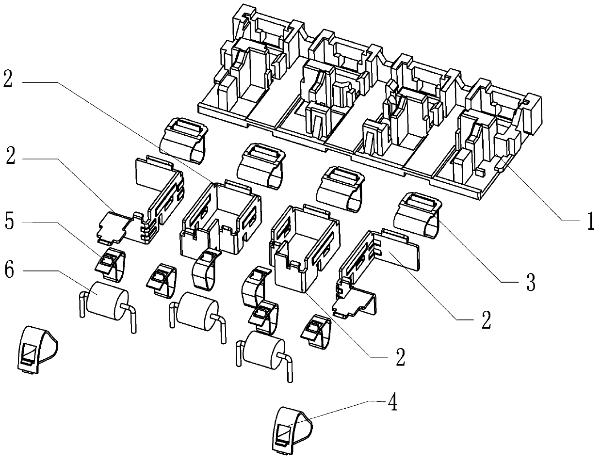
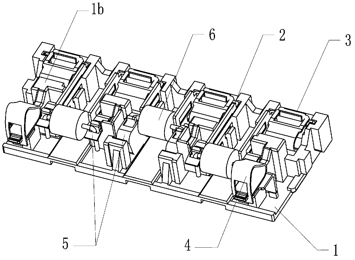
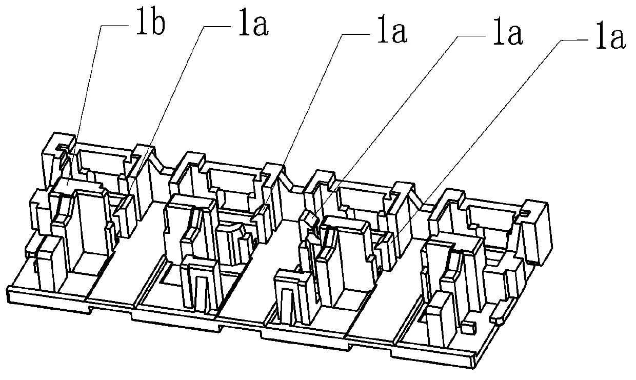
[0020] Such as figure 1 , figure 2 As shown, the present invention includes a mounting plate 1 fixed in a box body (not shown in the figure), on which a plurality of flow guide strips 2 are fixed, and various triangular springs are installed on the flow guide strips 2, including belt Clip triangular spring 3, line clip triangular spring 4 and tube clip triangular spring 5. The triangular spring 3 with clip is installed on the front end of each diversion strip 2, the triangular spring 4 of the cable clip is installed on the tail end of the two outermost diversion strips 2, and the triangular spring 5 of the pipe clip is installed on the end of each diversion strip 2 middle part. The diode 6 is installed between the tube clip triangular springs 5 ​​of two adjacent flow guide bars 2 .

[0021] exist figure 1 , figure 2 In the shown embo...


PUM


Abstract

The invention discloses a heat-dissipation optimization type photovoltaic terminal box which comprises a mounting plate fixed in a box body, wherein a plurality of current guide strips are fixed on the mounting plate; a strap clamp triangular spring, a cable clamp triangular spring and a pipe clamp triangular clamp are mounted on each current guide strip; and a diode is mounted between every two pipe clamp triangular clamps of adjacent current guide strips. According to the heat-dissipation optimization type photovoltaic terminal box, the diodes on the mounting plate are distributed in a staggered manner and located on different straight lines, so that heat is relatively dispersive; a heat distance of pins of the diodes of the same current guide strip is far, so that the heat conduction and dissipation space is enlarged; and the pins of the middle diodes are clamped and connected through the pipe clamp triangular springs and further sufficiently contacted with the current guide strips so as to form second connecting points. The invention further designs a buckled position fixing structure of the current guide strips and the mounting plate, bosses are arranged on the mounting plate, and the strap clamp triangular springs and the pipe clamp triangular springs can be conveniently levered with the bosses serving as pivots, so that the terminal box is convenient to mount and dismount.

Description

technical field [0001] The invention relates to the field of photovoltaic power generation, in particular to a heat dissipation optimized photovoltaic junction box applied in a photovoltaic power generation system. Background technique [0002] In the electrical connection technology of photovoltaic power generation systems, photovoltaic junction boxes are usually used to realize the electrical connection between photovoltaic modules and inverters. Currently commonly used photovoltaic junction boxes are provided with an installation cavity between the box bodies, and conductive sheets with diodes are installed in the installation cavity. Since the diode will generate a higher temperature during operation, as the temperature of the diode continues to rise, the resistance in the diode will continue to increase, causing the diode to generate more heat, thereby wasting more power resources and entering a vicious circle . In order to ensure better heat dissipation of the photov...

Claims


Application Information

Patent Timeline
Patent Type & Authority Applications(China)
IPC IPC(8): H01L31/048H01L31/052
CPCY02E10/50
Inventor 彭祁军李艳群
Owner 浙江正泰鑫辉光伏有限公司
Learn More