Wiring module

A technology of incoming line and busbar clips, which is applied in the direction of fully enclosed busbar devices, busbar/line layout, etc., can solve the problems of cumbersome assembly process, time-consuming and laborious, etc., and achieve the effect of simple assembly process, reducing labor cost and expanding space

Pending Publication Date: 2020-09-01
浙江金莱勒电气有限公司
View PDF0 Cites 0 Cited by
  • Summary
  • Abstract
  • Description
  • Claims
  • Application Information

AI Technical Summary

Problems solved by technology

[0004] Therefore, the technical problem to be solved by the present invention is to overcome the cumbersome assembly process in the prior art, time-consuming and labor-intensive defects, thereby providing a simple and quick assembly of a wiring module

Method used


Image

  • Wiring module
  • Wiring module
  • Wiring module

Examples


Embodiment

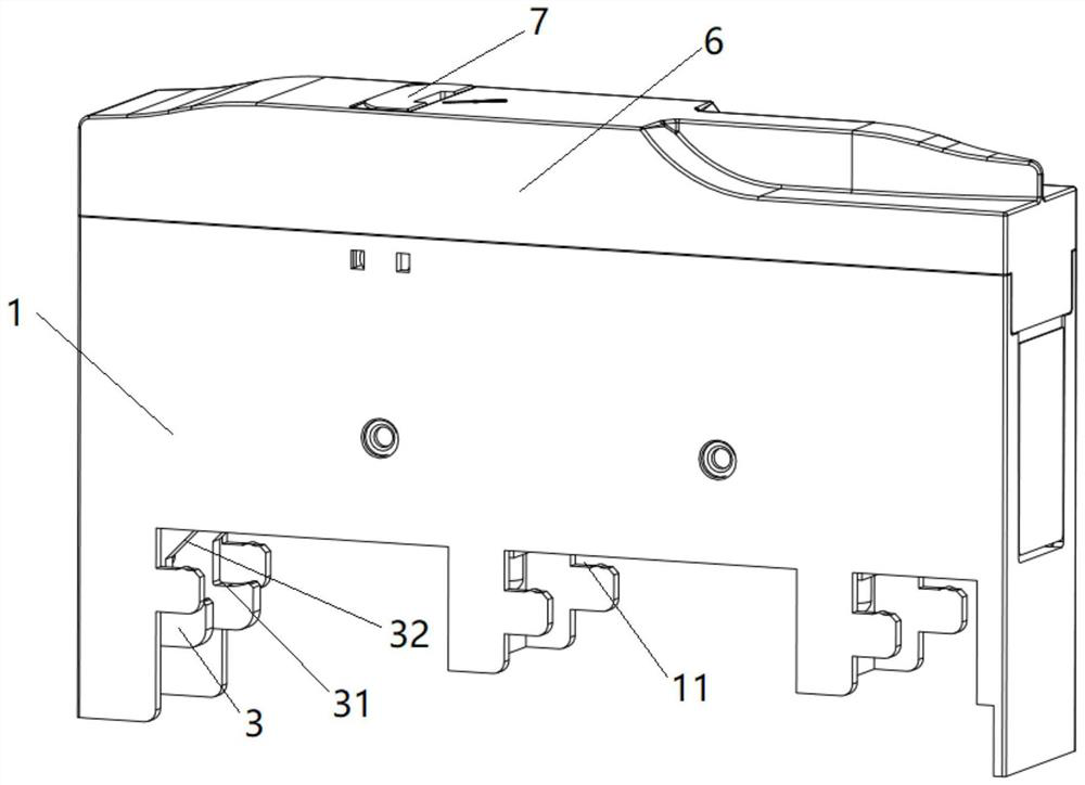
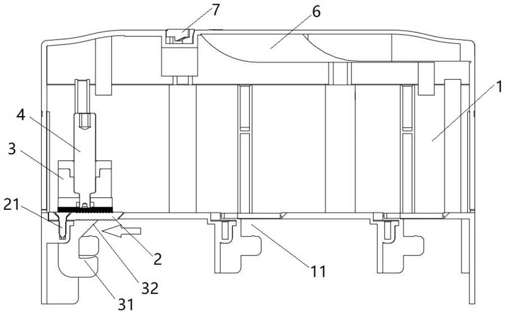
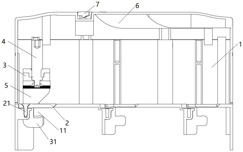
[0044] This embodiment provides a wiring module, such as figure 1 with 2 As shown, it includes base 1, contact piece 2, bus bar clamp 3, cover plate 6 and locking piece 7.

[0045] Base 1, such as figure 1 , 4 , 5, the bottom of which is provided with a slot 11 for the insertion of the incoming busbar, and an installation step 15 located below the slot 11. The installation step is provided with a protrusion for preventing the incoming busbar from detaching after it is inserted. 16, two slide grooves 12 are arranged on the two inner sides opposite to each other on the base 1, and the slide grooves 12 extend along the vertical direction, and two second insertion slots are arranged on the inner side of the base 1. hole 13, and two limiting holes 14 are formed on the inner wall of the second insertion hole 13.

[0046] Contact 2, such as figure 2 As shown, it is fixed on the base 1 by screws 21, and is located in the middle of the clamping cavity of the busbar clamp 3, and...


PUM


Abstract

The invention provides a wiring module. A bus clamp is provided with a bolt pressing plate assembly arranged at the upper part of the contact piece, and a clamping piece which is arranged at the lowerpart of the contact piece and is suitable for clamping an incoming line busbar; and a bolt pressing plate assembly and a contact piece are opposite to form a wire clamping cavity suitable for clamping an outgoing cable. The bus clamp is connected with the base through a guide structure; the bus clamp can be in sliding connection with the incoming line busbar through a combination structure; and the bus clamp is provided with a first position where the bolt pressing plate assembly abuts against the contact piece, and a second position which can move upwards relative to the contact piece underthe action of the incoming line busbar and the base; during assembly, the incoming line busbar is firstly inserted into the slot on the base; in the insertion process, the bus clamp can move upwards relative to the contact piece under the action of the incoming line busbar and the base guide structure, and then the bolt pressing plate assembly is driven to move upwards relative to the contact piece, so that the space of the wire clamping cavity is enlarged, an outgoing cable can be inserted conveniently, the assembly process is simpler, time and labor are saved, and the labor cost is reduced.

Description

technical field [0001] The invention relates to the technical field of low-voltage closed busbar systems, in particular to a connection module. Background technique [0002] Electrical equipment widely uses wiring modules to connect incoming busbars and outgoing cables, such as Figure 9-11 As shown, the junction module includes a housing, and a bus clamp 02 arranged in the housing 01 for clamping the incoming busbar and the outgoing cable. The bus clamp 02 includes a bus clamp body 021 and a bolt clamp assembly arranged above it. 022 and the connection plate 023 located in the middle, the connection plate 023 is fixed on the housing 01, the connection plate 023 is opposite to the bolt clamp assembly 022 above it to form the first clamping cavity 03 suitable for installing outgoing cables, and the connection The plate 023 is opposite to the splint part 04 located below it to form a second clamping cavity 05 suitable for installing the incoming busbar. When assembling, tighte...

Claims


Application Information

Patent Timeline
Patent Type & Authority Applications(China)
IPC IPC(8): H02B1/20H02G5/06
CPCH02B1/20H02G5/06
Inventor 刘德先
Owner 浙江金莱勒电气有限公司
Why Eureka
Try Eureka