
Digitized real-time magnetic field compensation device and method on basis of super-conducting magnetic sensor

A technology of a magnetic compensation device and a magnetic sensor is applied in the field of superconducting applications to achieve the effect of improving maintainability, increasing flexibility and maintainability, and achieving simplicity

Active Publication Date: 2013-11-13
SHANGHAI INST OF MICROSYSTEM & INFORMATION TECH CHINESE ACAD OF SCI
View PDF5 Cites 44 Cited by
  • Summary
  • Abstract
  • Description
  • Claims
  • Application Information

AI Technical Summary

Problems solved by technology

[0007] In order to solve the limitations of the existing magnetic compensation method in sports and field environments, and aim at the application fields where there are differences in the frequency bands of the signals to be compensated and to be measured, the purpose of the present invention is to provide a magnetic sensor composed of a digital circuit and a traditional magnetic flux locked loop. The second-order negative feedback system realizes the external disturbance magnetic field real-time automatic compensation device and method. The method provided by the invention can not only simplify the magnetic compensation device, but also realize digitization, automation and soft start conveniently, thereby improving the flexibility and reliability of the magnetic compensation device. sex

Method used


Image

  • Digitized real-time magnetic field compensation device and method on basis of super-conducting magnetic sensor
  • Digitized real-time magnetic field compensation device and method on basis of super-conducting magnetic sensor
  • Digitized real-time magnetic field compensation device and method on basis of super-conducting magnetic sensor

Examples


Embodiment Construction

[0021] In order to make the purpose, specific solutions and advantages of the present invention clearer, the present invention will be further described in detail below in conjunction with specific embodiments and with reference to the accompanying drawings.

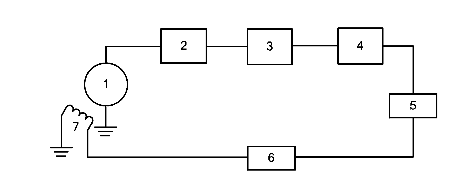
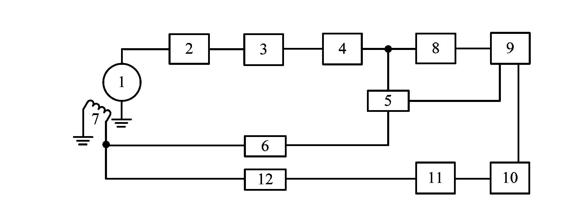
[0022] like figure 1The traditional flux-locked loop readout circuit shown is used to complete the measurement of the magnetic signal to be measured, and its main structure is as follows: the SBC superconducting magnetic sensor 1 placed in Dewar liquid helium is connected to the front-end amplifier 2 through a cryogenic cable, Wherein the SBC superconducting magnetic sensor 1 has two kinds of working modes: current bias and voltage bias, the present invention adopts the voltage bias mode, and the front-end amplifier 2 then selects the reverse amplifier that gain is 80~100dB, and its output will be affected by SBC There is a DC voltage offset in the electrical characteristics of the superconducting magnetic sensor 1, so t...


PUM


Abstract

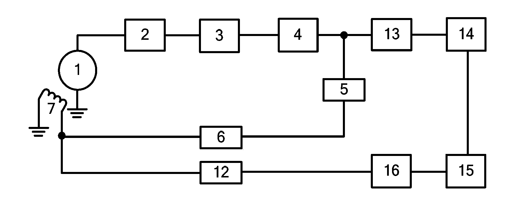
The invention relates to a digitized real-time magnetic field compensation device and method on the basis of a super-conducting magnetic sensor. The digitized real-time magnetic field compensation device is characterized by leading in two-stage negative feedback with different passing band characteristics on the basis of a traditional magnetic flux locking ring reading circuit to achieve reading of high-sensitivity to-be-measured magnetic field signals and compensation of low-sensitivity to-be-compensated magnetic field interference, adopting a digital circuit composed of an analog-to-digital converter (ADC), a microprocessor, a digital-to-analog converter (DAC) and accessories thereof to form a magnetic compensation circuit, and adding soft start capable of improving reliability of the magnetic compensation device and a function of automatic direct current offset eliminating of a magnetic flux locking ring. The compensation method is characterized by collecting output signals of the magnetic flux locking ring through the ADC, performing direct current offset elimination, filtering, inversion and integration through the microprocessor and finally outputting signals required by magnetic compensation through the DAC. A SQUID Feedback ring is used for feedback, so that the structure of the magnetic compensation device is greatly simplified, and maintainability, reliability and to-be-compensated signal withdrawing capability of the magnetic compensation device are improved.

Description

technical field [0001] The invention relates to a magnetic field compensation device and method of a superconducting magnetic sensor, in particular to a method for realizing real-time compensation of an external disturbance magnetic field by forming a second-order negative feedback system through a digital circuit and a traditional magnetic flux locking loop. It belongs to the technical field of superconducting applications. Background technique [0002] The superconducting magnetic sensor composed of a superconducting quantum interferometer (SQUID) is currently the most sensitive magnetic sensor known. It has been used in many applications in magnetically shielded rooms and static working environments. The magnetic field interference introduced by external factors such as the drift of the earth's magnetic field or the cutting of the earth's magnetic force lines can easily cause the baseline drift or even overflow of the highly sensitive SQUID readout circuit to fail to work...

Claims


Application Information

Patent Timeline
IPC IPC(8): G01R33/035
Inventor 伍俊荣亮亮王会武王永良常凯侍文董慧蒋坤谢晓明
Owner SHANGHAI INST OF MICROSYSTEM & INFORMATION TECH CHINESE ACAD OF SCI
Learn More