
Novel 10-gear double-intermediate-shaft synchronizer gearbox

A technology of double countershafts and synchronizers, which is applied to transmission parts, gear transmissions, belts/chains/gears, etc., can solve the problems of low assembly bearing capacity, driver fatigue, and small synchronization capacity, and achieve reduction The effect of shifting force, improving the load capacity of the main box, and reducing meshing noise

Active Publication Date: 2013-11-13
SINO TRUK JINAN POWER
View PDF7 Cites 2 Cited by
  • Summary
  • Abstract
  • Description
  • Claims
  • Application Information

AI Technical Summary

Problems solved by technology

In order to ensure the accuracy of tooth alignment, the main box gear generally adopts straight tooth gear, which has the disadvantages of low assembly load capacity and high noise; the main box part generally uses meshing sleeves to shift gears and convert from one transmission ratio to another. When shifting, because the meshing line speeds of a pair of gears or meshing sleeves to be meshed during shifting are not equal, there will be impact and noise during meshing, and in severe cases, it will even cause damage to the gear teeth, resulting in early wear of the main box; corresponding to the above structure, the driver needs to pay a large shift force to complete the shift quickly and correctly in a short time during operation, so the driver is prone to fatigue; the auxiliary box generally uses a short-stroke single-taper lock ring synchronizer to shift gears , small synchronous capacity, easy to cause early damage

Method used


Image

  • Novel 10-gear double-intermediate-shaft synchronizer gearbox
  • Novel 10-gear double-intermediate-shaft synchronizer gearbox
  • Novel 10-gear double-intermediate-shaft synchronizer gearbox

Examples


Embodiment Construction

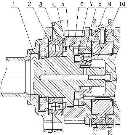
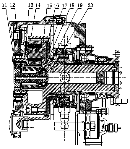
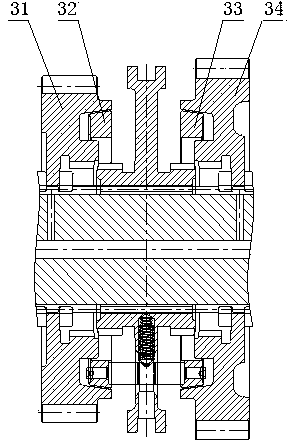
[0016] The specific implementation manners of the present invention will be described below in conjunction with the accompanying drawings. The novel 10-speed helical double countershaft synchronizer gearbox disclosed in the present invention includes a main box part A and an auxiliary box part B. The main box part A is provided with an input shaft 5 and a main shaft 10 connected to the input shaft 5. The main shaft 10 The spline transition sleeve 11 is connected with the sun gear 13 in the sub-box part B. The front and rear ends of the main shaft 10 are respectively provided with a main shaft front positioning mechanism and a main shaft rear positioning mechanism. The main shaft 10 is provided with a shift helical gear set; The middle main shaft 10 is provided with a single-cone lock ring synchronizer C between the fourth and fifth gears, a single-cone lock-pin synchronizer D between the second and third gears, and a reverse one between the first and second gears. Gear double ...


PUM


Abstract

The invention discloses a novel 10-gear double-intermediate-shaft synchronizer gearbox, which comprises a novel three-section shell, an input shaft and a main shaft connected with the input shaft, wherein the main shaft is connected with a sun wheel in a sub-box through a spline taper reduction sleeve, the front end and the rear end of the main shaft are provided with a main shaft front positioning mechanism and a main shaft rear positioning mechanism respectively, the main shaft is also provided with a gear-shifting bevel gear group which comprises five forwarding bevel gears and a reversing bevel gear, a single-cone lock ring synchronizer is arranged between the fourth gear and the fifth gear on the main shaft, a single-cone lock pin synchronizer is arranged between the second gear and the third gear on the main shaft, a twin cone lock pin synchronizer is arranged at the first gear on the main shaft, the sub-box part comprises two gear positions and forms a 5*2 structure of ten forward gears and two reverse gears with a main box part, and a planetary gear train mechanism and a widened twin cone lock ring synchronizer are arranged in the sub-box part. The gearbox has the advantages that the operation is labor-saving, the gear shifting operation and the transmission are smooth, the noise is small, and the physical life is prolonged.

Description

technical field [0001] The invention relates to a gearbox, in particular to a novel 10-speed dual countershaft synchronizer gearbox. Background technique [0002] At present, in the common double countershaft heavy-duty truck gearbox structure, it is necessary to align the teeth of the two countershaft gears to ensure the consistency of the two countershaft assemblies. In order to ensure the accuracy of tooth alignment, the main box gear generally adopts straight tooth gear, which has the disadvantages of low assembly load capacity and high noise; the main box part generally uses meshing sleeves to shift gears and convert from one transmission ratio to another. When shifting, because the meshing line speeds of a pair of gears or meshing sleeves to be meshed during shifting are not equal, there will be impact and noise during meshing, and in severe cases, it will even cause damage to the gear teeth, resulting in early wear of the main box; corresponding to the above structur...

Claims


Application Information

Patent Timeline
IPC IPC(8): F16H3/12F16H57/023F16H57/021
Inventor 王辉胡凯杨伟玲任宪群
Owner SINO TRUK JINAN POWER
Learn More