Eureka AIR delivers breakthrough ideas for toughest innovation challenges, trusted by R&D personnel around the world.

Implement method for plane micro-strip linear high-distribution ratio unequal power divider

A technology of a power divider and a realization method, which is applied in the directions of waveguide-type devices, electrical components, connecting devices, etc., can solve the problems of large characteristic impedance of transmission lines, difficult manufacturing, and difficulty in realizing high characteristic impedance, and achieves advantages of circuit size and difficulty. The effect of advantage

Inactive Publication Date: 2013-11-06
CNGC INST NO 206 OF CHINA ARMS IND GRP
View PDF4 Cites 5 Cited by
  • Summary
  • Abstract
  • Description
  • Claims
  • Application Information

AI Technical Summary

Problems solved by technology

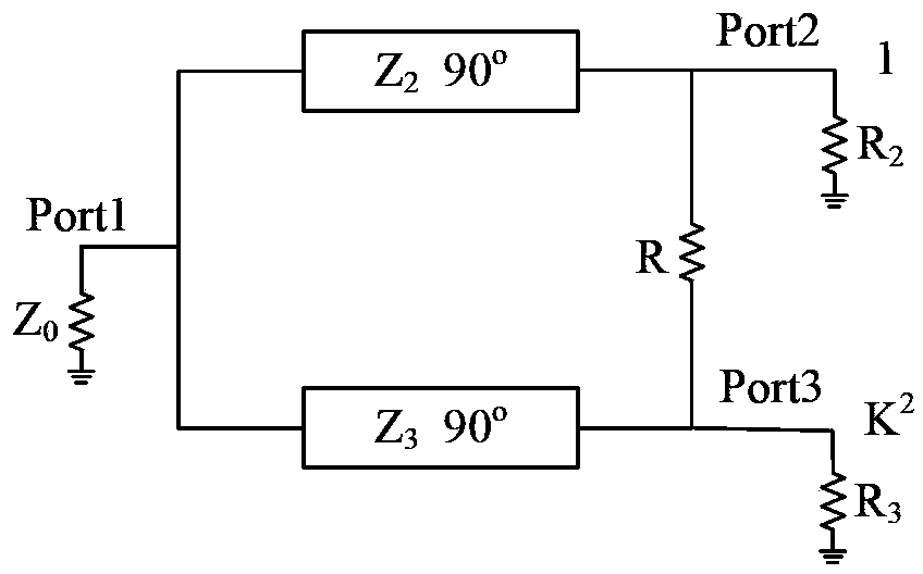
[0036] It can be seen from formula 9 that when the power distribution ratio K 2 ≥3, transmission line Z 2 The characteristic impedance of the microstrip line becomes very large. Due to the limitation of the processing technology, the characteristic impedance of the microstrip line can only be 120Ω~130Ω at the highest. If the characteristic impedance is too high, it will be difficult to achieve because the line width is too narrow.
[0037] In the case of high power distribution ratio, due to the limitation of the processing line width, it is difficult for the traditional microstrip Wilkinson power divider to achieve high characteristic impedance
In the existing technology, the use of double-sided parallel transmission line DSPSL (Double-Side Parallel-Strip line) can solve this problem, but the combination of DSPSL and microstrip line will introduce additional insertion loss and increase the circuit size; in addition, a A non-ideal ground plane structure using DGS (Defected Ground Structure) can enable a wider microstrip line width to achieve higher characteristic impedance, but it is much more difficult to manufacture than traditional microstrip lines

Method used


Image

  • Implement method for plane micro-strip linear high-distribution ratio unequal power divider
  • Implement method for plane micro-strip linear high-distribution ratio unequal power divider
  • Implement method for plane micro-strip linear high-distribution ratio unequal power divider

Examples


Embodiment Construction

[0065] Now in conjunction with embodiment, accompanying drawing, the present invention will be further described:

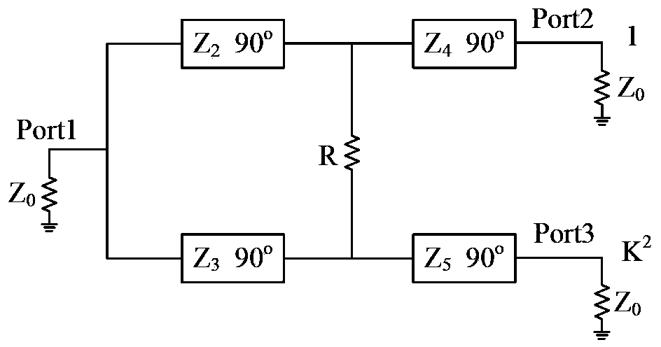
[0066] In this embodiment, an arbitrary positive real number C with a unit of Ω is introduced, and the figure 1 The external load resistance in the change into R 2 = K 2 ×C and R 3 =C. And if image 3 As shown in , the length of the two sections is a quarter wavelength, and the characteristic impedance is Z 4 and Z 5 The transmission line is used to connect R 2 and R 3 Transform to Z 0 (50Ω).

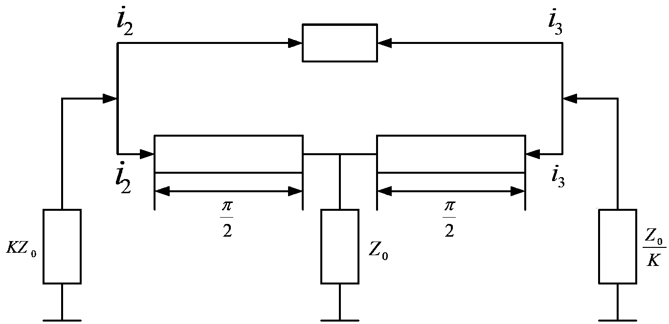
[0067] It can be seen from the background knowledge that the design of the unequal power divider must meet the following two conditions: the output power of port 3 is the K of port 2 2 The voltage between port 2 and port 3 is equal to the ground respectively, so the characteristic impedance of all transmission line segments in port 2 must be K of the characteristic impedance of the transmission line segment corresponding to port 3 2 times. And using the matchin...


PUM


Abstract

The invention relates to an implement method for a plane micro-strip linear high-distribution ratio unequal power divider. Excessively high characteristic impedance is lowered by introducing the method of an improvement factor C, and a 'T'-shaped structure is used for replacing a quarter-wave transmission line with excessively low characteristic impedance, so that the line width of each microstrip line is in a reasonable range, and the difficulty in manufacturing the high-distribution ratio unequal power divider with a traditional plane microstrip line is solved. Moreover, compared with the prior art utilizing a double sided parallel strip line (DSPSL) or a non-ideal plane structure (DGS), the implement method has advantages in manufacturing cost and difficulty and circuit dimension.

Description

technical field [0001] The invention belongs to the field of microwave radio frequency circuits, and in particular relates to a method for realizing a planar microstrip line-type power divider with high distribution ratio and unequal ratio, which is applied to power distribution and power combining planar microstrip circuits requiring a high power distribution ratio. Background technique [0002] Power dividers are microwave passive devices used in power distribution and power combining circuits. The microstrip power divider is small in size and easy to integrate, so it is widely used in radio frequency microwave integrated circuits. In radio frequency circuits, there is often a demand for unbalanced distribution of radio frequency power, so the unequal microstrip power divider has important application value in practical radio frequency circuits. Due to its simple structure, the Wilkinson type power divider is more widely used. [0003] figure 1 It is the schematic diagr...

Claims


Application Information

Patent Timeline
Patent Type & Authority Applications(China)
IPC IPC(8): H01P5/16
Inventor 张春荣芦嘉马汉清余铁军李建玲李兵王栋荀民
Owner CNGC INST NO 206 OF CHINA ARMS IND GRP
Why Eureka
Eureka Blog
Learn More