
Drilling head separating floor anchoring drill

A separate, bottom-plate technology, used in earth-moving drilling, wellbore/well components, flushing wellbore, etc., can solve the problems of reducing support efficiency, waste of water resources, affecting bolt support, etc., and achieve improved support Efficiency, speed up construction, reduce the effect of surrounding rock strength

Active Publication Date: 2013-11-06
CHINA UNIV OF MINING & TECH
View PDF5 Cites 4 Cited by
  • Summary
  • Abstract
  • Description
  • Claims
  • Application Information

AI Technical Summary

Problems solved by technology

This kind of wet drilling method has some technical problems when working on the coal mine floor: first, the extruded mud-water mixture splashes around with the drill pipe and cannot be collected, which affects the normal transportation of the roadway and the walking of workers, and at the same time, the surrounding rock of the floor is soaked and softened The bottom drum problem is exacerbated; secondly, the traditional drilling method is easy to cause hole plugging in the floor construction, and the drilling back and hole cleaning work is extremely cumbersome during the drilling process, which seriously affects the construction efficiency of the floor anchoring; thirdly, if the wet method is used The drilling method is used to drill holes in the bottom plate of the roadway. The bottom plate will be filled with a lot of water and rock powder, which will affect the bolt support, reduce the support efficiency, and cause a lot of waste of water resources; fourth, in the working condition In roadways with bad or restricted water sources, the wet dust removal system cannot work normally, and the coal (rock) powder in the drilled holes enters the roadway, which intensifies the difficulty of dust control in the roadway and endangers the health of workers

Method used


Image

  • Drilling head separating floor anchoring drill

Examples


Embodiment Construction

[0011] An embodiment of the present invention will be further described below in conjunction with accompanying drawing:

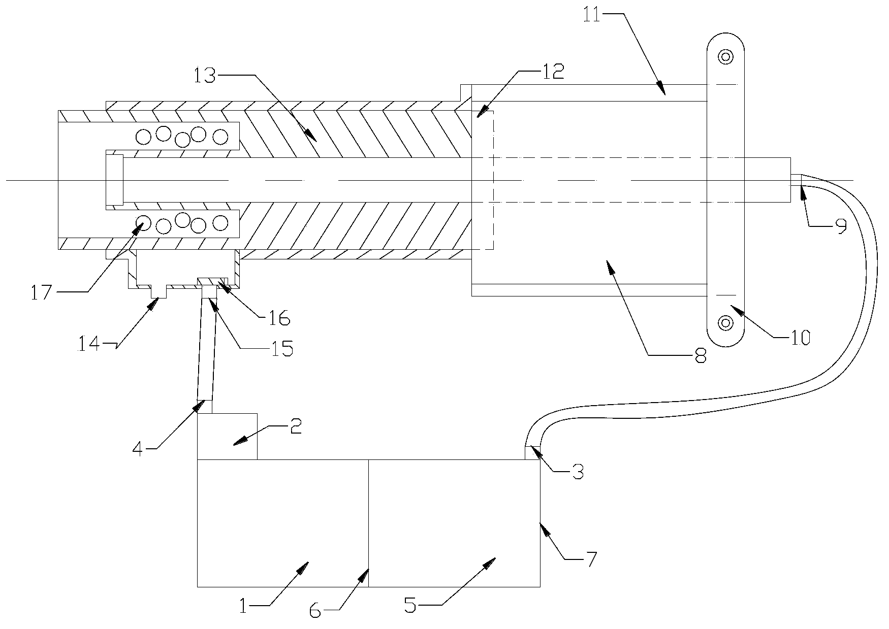
[0012] The drilling platoon separation floor anchoring drilling rig of the present invention is mainly composed of a pumping pump 2, a separation water-rock circulator 7, a motor 8, a sewage suction port 9, a bracket connector 10, a muffler 11, and a speed controller 12. The end of the motor 8 is provided with a bracket connector 10 , the bottom of the motor 8 is provided with a suction port 9 , the front end of the motor 8 is provided with a speed controller 12 , and the periphery of the motor 8 is provided with a muffler 11 . The front end of the speed governor 12 is provided with a hollow transmission shaft 13, the front portion of the hollow transmission shaft 13 is provided with an annular groove, and a plurality of water inlet holes 17 are arranged in the annular groove, and the bottom of the hollow transmission shaft 13 is provided with a water inlet ...


PUM


Abstract

The invention discloses a drilling head separating floor anchoring drill which comprises a water-rock separating circulator, a hydraulic pump, a motor, a silencer, a velometer, a soil pickup outlet and a hollow transmission shaft. Water inlet holes are formed in the hollow transmission shaft, water is injected into the bottom of a drilled hole through the water inlet holes, the temperature of a drill bit is reduced, and dust is removed. The water-rock separating circulator is divided into a clear water tank and a mud tank by a filter screen, the hydraulic pump is mounted on the upper portion of the water-rock separating circulator, mud (rock powder and water mixture) in the drilled hole is pumped into the mud tank by the hydraulic pump, clear water enters the clear water tank after the mud is filtered, and the clear water is pumped into a water inlet tank by the hydraulic pump and recycled through a clear water inlet hole. Waste of water resources is avoided, rock powder generated in drilling is collected, sticking in drilling of the drill is prevented, the dust is prevented from harming health of workers, the water and the rock powder in the drilled hole are timely pumped out, the water is prevented from weakening floor lithology, and support efficiency is improved. Operation is facilitated, and construction is easily performed.

Description

technical field [0001] The invention relates to the technical field of mining equipment, in particular to a drilling rig separation type floor anchoring drilling rig. Background technique [0002] With the rapid development of my country's economic construction, the demand for energy is huge. Coal resources, as the main source of energy supply in my country, will be difficult to change for a long time in the future, resulting in the continuous development of the coal industry in the direction of mechanization and automation. In most coal mines in my country, due to the nature of coal and rock, depth of burial, and ground stress, the floor of the roadway is seriously damaged, which affects the use of the roadway and restricts the safe production of the mine. Therefore, the task of floor reinforcement and treatment is arduous. [0003] At this stage, bolt support is the most effective means of strengthening and controlling coal mine floor. At present, there are few domestic a...

Claims


Application Information

Patent Timeline
IPC IPC(8): E21B21/00E21B21/06
Inventor 马占国蒋众喜王泽民张帆李强德王秀林周玉海刘占斌张金亮王坤
Owner CHINA UNIV OF MINING & TECH
Learn More