Connector

一种连接器、腔室的技术,应用在连接器领域,能够解决易于破损、撞杆破损等问题,达到避免损伤、实现小型化的效果

Active Publication Date: 2013-10-30
SUMITOMO WIRING SYST LTD
View PDF5 Cites 13 Cited by
  • Summary
  • Abstract
  • Description
  • Claims
  • Application Information

AI Technical Summary

Problems solved by technology

However, when the front end of the lance is cut out to reduce the size, after foreign matter enters the chamber from the front, the front end of the lance may be disturbed by the foreign matter and be damaged.
Especially when the terminal fitting stays in the cavity in a half-inserted state, and the lance maintains a deflected state, when the retainer enters the cavity from the front, sometimes the front end of the lance hits the front end of the retainer. and the problem of easy breakage

Method used


Image

  • Connector
  • Connector
  • Connector

Examples


Embodiment Construction

[0035] The present invention can be embodied as follows.

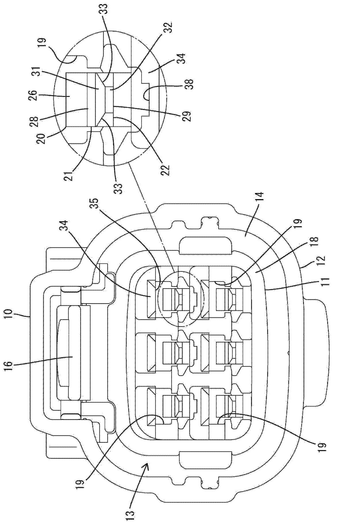
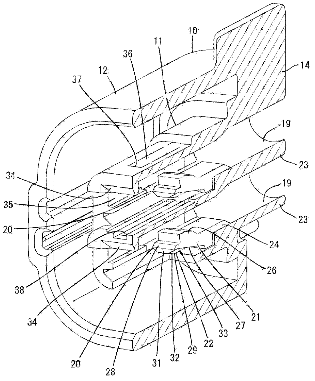
[0036] On the inner surface of the chamber at a position opposite to the second inclined surface, a concave portion is formed into which the inclined portion enters when the lance main body flexes and deforms. Thereby, a large amount of deflection of the lance main body can be ensured, and at the same time, the casing portion can be sufficiently reduced in size.

[0037] A through hole penetrating along the deflection direction of the lance main body is formed at a position of the housing part facing the lance main body, and a terminal that prevents the second time by restricting the bending movement of the lance main body is attached to the housing part from the front. The retainer from which the accessories come off has a locking protrusion that fits elastically into the through hole and locks with the front end of the through hole, thereby preventing the retainer from falling off from the housing. For example, when...


PUM


Abstract

A locking lance (20) on the inner surface of a cavity (19) of a housing (11) includes a lance main body (21) and an inclined portion (22). The lance main body (21) is cantilevered forward toward the center of the cavity (19) from the inner surface of the cavity (19). The inclined portion (22) is connected to a front part of the lance main body (21) and is narrower than a rear part of the lance main body (21). A first inclined surface (31) of the inclined portion (22) faces the interior of the cavity (19) and inclines away from the center of the cavity (19) to the front. A second inclined surface (32) is opposite the first inclined surface (31), inclines toward the center of the cavity (19) to the front, and is tapered so that the first inclined surface (31) becomes gradually narrower toward the front.

Description

technical field [0001] The present invention relates to connectors. Background technique [0002] Patent Document 1 discloses a conventional connector. This connector includes: a housing portion having a cavity; and a flexible plunger protruding forward in a cantilever shape from the inner surface of the cavity toward the center side of the cavity. In the chamber, the terminal fittings are inserted from the rear, and the normally inserted terminal fittings are elastically prevented from coming off by the lance. [0003] Patent Document 1: Japanese Patent Application Publication No. 7-34569 [0004] However, when miniaturization of the connector is required, for example, when the lance is miniaturized as a whole, the holding force of the lance for the terminal fitting decreases, and the terminal fitting may come loose from the cavity. In view of this, for example, the front end of the lance is notched so as to recede from the inner surface of the chamber, and the front end...

Claims


Application Information

Patent Timeline
Patent Type & Authority Applications(China)
IPC IPC(8): H01R13/40H01R13/46
CPCH01R13/4223H01R13/4364
Inventor 郑松田中努
Owner SUMITOMO WIRING SYST LTD
Why Eureka
Try Eureka