Constant Force Mechanism, Movement And Timepiece

A movement and power source technology, applied to clocks, clock drive mechanisms, mechanically driven clocks, etc., can solve problems such as inability to ensure deflection, reduced timing accuracy, and large changes in deflection and torque, and achieve good results. Timing accuracy, ensuring timing accuracy, and the effect of stable driving

Active Publication Date: 2016-03-16
SEIKO INSTR INC
View PDF5 Cites 3 Cited by
  • Summary
  • Abstract
  • Description
  • Claims
  • Application Information

AI Technical Summary

Problems solved by technology

[0006] However, in the prior art, since the spring for torque adjustment is formed of a leaf spring, a sufficient amount of deflection cannot be ensured, and the change in torque per unit amount of deflection becomes large.
Therefore, there is a concern that when the constant force mechanism operates, the torque fluctuation rate due to the change in the urging force of the torque adjustment spring increases, and the timing accuracy decreases.

Method used


Image

  • Constant Force Mechanism, Movement And Timepiece
  • Constant Force Mechanism, Movement And Timepiece
  • Constant Force Mechanism, Movement And Timepiece

Examples


Embodiment Construction

[0032] Hereinafter, embodiments of the present invention will be described with reference to the drawings.

[0033] Generally, the mechanical body including the driving part of the timepiece is called the "movement". The state in which the dial and the hands are mounted on the movement and put into the watch case to become a finished product is called the "complete" of the watch. Among the two sides of the bottom plate of the substrate constituting the timepiece, the side where the glass of the timepiece case is present, that is, the side where the dial is present is referred to as the "back side" of the movement. In addition, among the two sides of the bottom plate, the side where the case back cover of the watch case exists, that is, the side opposite to the dial is referred to as the "front side" of the movement.

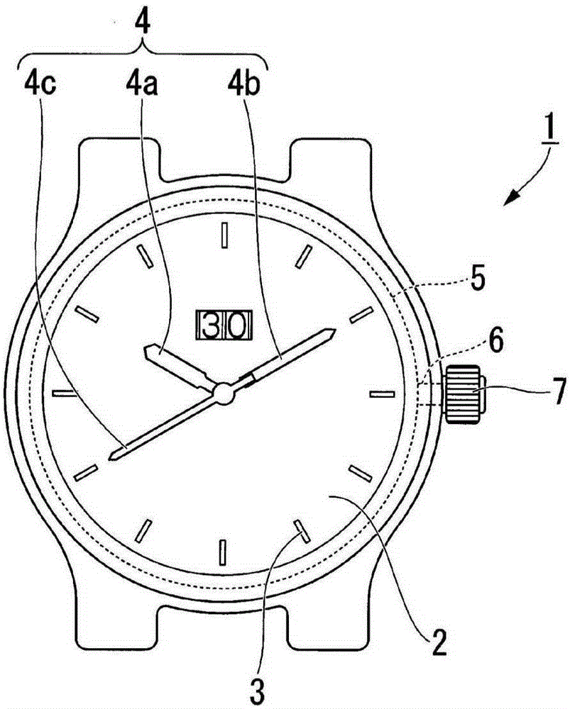
[0034] figure 1 It is a top view of the clock 1.

[0035] Such as figure 1 As shown, the timepiece 1 includes a dial 2 including a scale 3 and the like, and the scale...


PUM


Abstract

The invention provides a constant force mechanism, a movement and a timepiece that can ensure a sufficient amount of deflection of a torque adjusting spring and that can ensure measurement accuracy of the time. The constant force mechanism comprises: a portion of power switch (11), which is incorporated in a drive train (70) from a driving wheel on barrel of a power source to a release catch; a pivot lever (20), which supports the part of power switch (11) so as to allow it to rotate about a first axis (C1); and a cycle control mechanism (30), which has a ratchet wheel (31) rotatable with the power (operating torque) transmitted from the driving wheel on barrel, a torque adjusting spring (40), which generats a pushing force by expansion and contraction and resulting in the release catch (60); and a locking portion (39), which is actuated by the torque adjusting spring (40) for locking the ratchet wheel (31), and the cycle control mechanism (30) is adapted to rotate the pivot lever (20) intermittently.

Description

Technical field [0001] The invention relates to a constant force mechanism, a movement and a clock. Background technique [0002] In mechanical timepieces, when the torque transmitted from the barrel wheel as the power source to the escapement changes according to the unwinding of the barrel of the barrel wheel (巻き解け), the swing angle of the balance with hairspring changes and the timepiece The speed changes. Therefore, in order to suppress the fluctuation of the torque transmitted to the escapement, a constant force mechanism in which a torque adjustment spring is arranged between the barrel wheel and the escapement has been proposed. [0003] For example, the constant force mechanism described in Patent Document 1 includes: a fixed wheel; a frame arm (Carriagearm) that rotates around the axis of the fixed wheel; and a torque adjustment spring that is connected to the frame arm via a link mechanism. The constant force mechanism described in Patent Document 1 uses a long leaf spr...

Claims


Application Information

Patent Timeline
Patent Type & Authority Applications(China)
IPC IPC(8): G04B1/22G04B17/28
CPCG04B1/225
Inventor 藤枝久
Owner SEIKO INSTR INC
Why Eureka
Try Eureka