
Internal reflective vacuum heat collector, forming device and close-packed heat collector

A vacuum heat collecting tube and forming device technology, which is applied in heating devices, solar thermal devices, forming tools, etc., can solve the problems of large heat capacity, light leakage, and water storage in heat collecting tubes, and achieve the effect of small heat capacity

Inactive Publication Date: 2015-11-04
李春信
View PDF8 Cites 0 Cited by
  • Summary
  • Abstract
  • Description
  • Claims
  • Application Information

AI Technical Summary

Problems solved by technology

There are certain defects in this type of heat collecting tubes. The specific performance is that due to the equal-diameter heat collecting tubes, due to the process, strength and other reasons, several heat collecting tubes cannot be densely arranged to connect to the water storage tank. There is a certain gap between the heat collecting tubes, which is the light leakage gap. , resulting in a decrease in the utilization rate of solar energy, which seriously affects the thermal energy efficiency of the solar water heater. The area occupied by the water heater is large, which restricts the installation and use of the water heater; also due to the existence of the light leakage gap, the gap does not have any effect on absorbing solar energy, and the invalid gap also It needs to correspond to the length of the water tank, the length of the bracket and the corresponding auxiliary materials for the production of the water heater. Therefore, the cost of labor and materials for the production of the water heater increases. Under the same heat gain, it is estimated that the waste of labor and material costs is about 18%. At the same time, the same diameter The inner tube has a large heat capacity, which is not conducive to the rapid conversion of heat energy. The traditional heat collecting tube has a lot of water stored in it and is not easy to be used, resulting in a low heat utilization rate of the heat collecting tube, and the temperature rise of the water in the water storage tank is limited. Therefore, it is usually only suitable for people's domestic water. It cannot be used in industrial fields that have high requirements for water temperature
In order to improve the thermal efficiency of the heat collector tube and the temperature of hot water, there are eccentric reflective tubes on the market. The inner wall of the outer tube is coated to reflect sunlight to the inner tube to increase the temperature of the inner tube. However, the production cost of the coating is high and the yield is low. From the theoretical analysis of the inner wall of the eccentric reflective tube The coating layer has no reflective focus and much light leakage. The temperature of the heat collecting tube has increased but the thermal efficiency is not high. After actual testing, the heat collecting tube coated on the inner wall of the outer tube is not as good as the ordinary heat collecting tube.

Method used


Image

  • Internal reflective vacuum heat collector, forming device and close-packed heat collector
  • Internal reflective vacuum heat collector, forming device and close-packed heat collector
  • Internal reflective vacuum heat collector, forming device and close-packed heat collector

Examples


Embodiment Construction

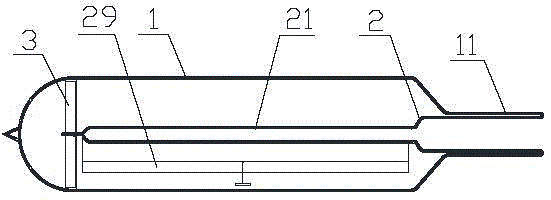
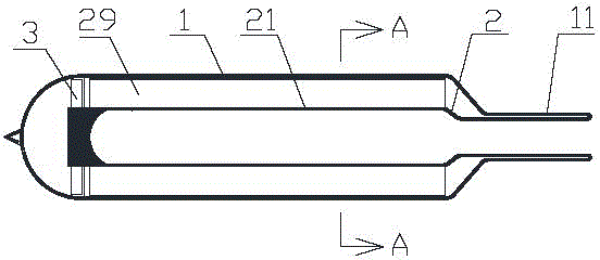
[0042] Such as figure 2 , image 3 with Figure 4 As shown, an internally reflective vacuum heat collecting tube of the present invention includes an outer tube 1, an inner tube 2 and a retaining spring 3, the inner tube 2 fits inside the outer tube 1, and the outer surface of the inner tube is coated with non- White selective light-to-heat conversion coating, the circlip 3 is arranged between the outer tube 1 and the inner tube 2 and is located at the tail end of the inner tube 2, the top ends of the outer tube 1 and the inner tube 2 are welded and sealed, and the outer The interlayer between the tube 1 and the inner tube 2 is a vacuum, and also includes a reflector 29. The diameter of the front section of the outer tube 1 is smaller than the diameter of the rear section to form a reduced diameter section 11, and the inner tube 2 is in the corresponding reduced diameter section of the outer tube 1. Below 11 is a flat tube 21, the reflector 29 is arranged in the interlayer ...


PUM


Abstract

The invention discloses an internal reflective evacuated collector tube, a forming device and a close-packed collector. An internal tube and an external tube of the internal reflective evacuated collector tube are sleeved, the top ends of the internal tube and the external tube are hermetically welded, the diameter of the front section of the external tube is smaller than that of the rear section of the external tube to form a reducing section, the internal tube below the reducing section of the external tube is a flat-plate tube, a reflecting plate is arranged between the internal tube and the external tube, a heat insulating cover of the forming device is arranged on a base, an upper forming mould and a lower forming mould are arranged in the heat insulating cover, an upper driving mechanism and a lower driving mechanism drive the upper forming mould and the lower forming mould to move, the end faces of the upper forming mould and the lower forming mould are provided with a circular tube section forming mould orifice and a flat-plate tube section forming mould orifice, and a flexible plastic crimping end is arranged on the flat-plate tube section forming mould orifice. A plurality of internal reflective evacuated collector tubes of the close-packed collector are connected with one side or two sides of a water storage tank, and the water storage tank and the internal reflective evacuated collector tubes are arranged on a support. The heat capacity of the internal reflective evacuated collector tube is low, the internal reflective evacuated collector tubes of the close-packed collector can be connected with the water storage tank in a close-packed manner, the forming device can be used for conveniently manufacturing the internal reflective evacuated collector tube, light leaking clearances are effectively reduced by the close-packed collector, and overall heat efficiency is improved.

Description

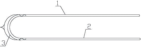
technical field [0001] The invention relates to a device in the field of solar photothermal technology, in particular to an internal reflective vacuum heat collecting tube for a solar water heater, a molding device and a densely packed heat collector. Background technique [0002] Solar water heaters convert sunlight energy into thermal energy and heat water from low temperature to high temperature to meet the hot water needs in people's lives. Solar water heaters are divided into vacuum tube solar water heaters and flat plate solar water heaters according to their structure. The vacuum tube solar water heater is composed of vacuum heat collecting tubes, water storage tanks and brackets and other related components. The conversion of solar energy into heat mainly depends on the heat collecting tubes. hot water. Such as figure 1 As shown, the general glass heat collecting tube is composed of an equal-diameter glass inner tube 2 and an equal-diameter glass outer tube 1. A v...

Claims


Application Information

Patent Timeline
Patent Type & Authority Patents(China)
IPC IPC(8): F24J2/46F24J2/04B21D37/10B21D37/16
CPCY02E10/44
Inventor 李佳雪李春信
Owner 李春信
Learn More