Hand clamp

A clamp and clamping technology, applied in the field of manual clamps, can solve the problems of clamp jamming, wear, loss of symmetry, etc., and achieve the effect of preventing jamming

Inactive Publication Date: 2013-10-30
潘素云
View PDF0 Cites 0 Cited by
  • Summary
  • Abstract
  • Description
  • Claims
  • Application Information

AI Technical Summary

Problems solved by technology

[0004] Clamps are a common hardware tool. The active part of the existing clamps is directly threaded on the fixed part. Due to wear and tear, after long-term use, the threads on the circumferential wall of the movable part will wear out and lose their symmetry. Sexuality, causing the clamp to stick and cannot be adjusted

Method used


Image

  • Hand clamp
  • Hand clamp
  • Hand clamp

Examples


Embodiment Construction

[0030] The preferred embodiments of the present invention will be described in detail below in conjunction with the accompanying drawings, so that the advantages and features of the present invention can be more easily understood by those skilled in the art, so as to define the protection scope of the present invention more clearly.

[0031] The invention provides a manual clamp.

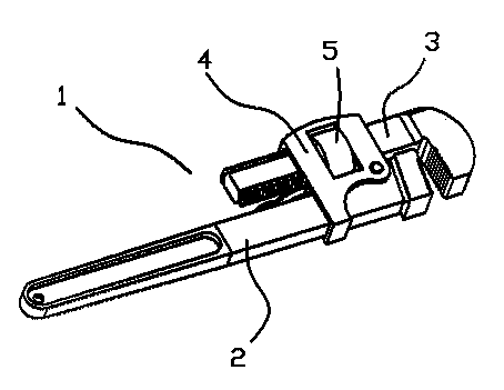
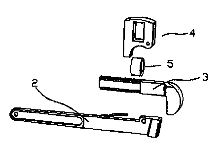
[0032] Such as Figure 1 to Figure 8 As shown, a manual clamp 1 includes a fixed part 2 and a movable part 3, the movable part 3 is movably connected with the fixed part 2 through a sleeve part 4, and an adjustment ring 5 is arranged in the sleeve part 4 , the movable part 3 passes through the adjusting ring 5 and is movably connected with the adjusting ring 5 .

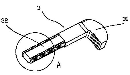
[0033] The movable part 3 includes an adjustment cavity 42 for accommodating the adjustment ring 5, and the adjustment cavity 42 includes a through installation through hole 421. The movable part 3 includes a clamping elbow 31 and a guide...


PUM


Abstract

The invention discloses a hand clamp comprising a fixing portion and a movable portion. The movable portion is movably connected with the fixing portion through a coupling portion. A regulating ring is arranged in the coupling portion. The movable portion penetrates the regulating ring and is movably connected with the same. Due to the fact that the movable portion of the hand clamp is connected with the fixing portion through the regulating ring and the coupling portion and a support reed is arranged on the fixing portion, when regulated by a user, the entire movable portion can keep the horizontal position without causing abrasion on partial faces, and the hand clamp is effectively prevented from being stuck.

Description

[0001] technical field [0002] The invention relates to a hardware tool, more specifically, a manual clamp. [0003] Background technique [0004] Clamps are a common hardware tool. The active part of the existing clamps is directly threaded on the fixed part. Due to wear and tear, after long-term use, the threads on the circumferential wall of the movable part will wear out and lose their symmetry. Sex, causing the clamp to stick and cannot be adjusted. [0005] Contents of the invention [0006] The present invention mainly solves the technical problems existing in the prior art, thereby providing a manual clamp. [0007] Above-mentioned technical problem of the present invention is mainly solved by following technical scheme: [0008] A manual clamp, comprising a fixed part and a movable part, the movable part is movably connected with the fixed part through a socket part, an adjustment ring is arranged inside the socket part, and the movable part The part pass...

Claims


Application Information

Patent Timeline
Patent Type & Authority Applications(China)
IPC IPC(8): B25B5/02B25B5/16B25B5/06
Inventor 潘素云
Owner 潘素云
Why Eureka
Try Eureka