
Solar cell

A technology of solar cells and back electrodes, which is applied in the field of solar cells, can solve problems such as low photoelectric conversion efficiency, affect cell efficiency, and enhance the extinction effect of solar cells, and achieve the effect of improving photoelectric conversion efficiency

Inactive Publication Date: 2013-10-23
ZHEJIANG ASTRONERGY
View PDF6 Cites 11 Cited by
  • Summary
  • Abstract
  • Description
  • Claims
  • Application Information

AI Technical Summary

Problems solved by technology

[0004] However, increasing Si x N y The refractive index of the film will enhance the extinction effect of the solar cell, which in turn will cause a decrease in the photoelectric conversion efficiency of the cell
while using SiO 2 / Si x N y When stacking composite films, due to the mismatch of refractive index between silicon dioxide and silicon nitride, the reflection of light will increase, and the increase of reflected light will inevitably lead to less light available for photoelectric conversion. thereby affecting the battery efficiency
In addition, it was found in the actual production process that in SiO 2 During deposition, due to insufficient H (hydrogen) content, the H passivation effect will not be fully reflected, so the current, voltage and fill factor of the solar cell will be significantly reduced, resulting in low photoelectric conversion efficiency of the cell
[0005] To sum up, in the prior art, there is no passivation layer that can realize PID-Free (free from potential difference-induced attenuation) of photovoltaic modules and can well solve the problem of low photoelectric conversion efficiency of cells

Method used


Image

  • Solar cell
  • Solar cell
  • Solar cell

Examples


Embodiment Construction

[0021] The following disclosure provides many different embodiments or examples for implementing different structures of the present invention. To simplify the disclosure of the present invention, components and arrangements of specific examples are described below. Furthermore, the present invention may repeat reference numerals and / or letters in different instances. This repetition is for the purpose of simplicity and clarity and does not in itself indicate a relationship between the various embodiments and / or arrangements discussed. It should be noted that components illustrated in the figures are not necessarily drawn to scale. Descriptions of well-known components and processing techniques and processes are omitted herein to avoid unnecessarily limiting the present invention.

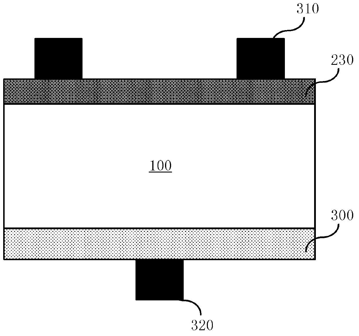
[0022] refer to image 3 , image 3 Shown is a schematic structural view of a specific embodiment of the solar cell provided by the present invention.

[0023] A silicon wafer 100 is provided....


PUM


Abstract

The invention discloses a solar cell. The solar cell sequentially comprises a back electrode, an aluminum back field, a silicon chip, a diffusion layer, a passivation layer and a positive electrode from bottom to top, and the passivation layer is a silicon oxynitride single layer or a silicon oxynitride / silicon nitride laminated structure, wherein silicon oxynitride is formed by depositing N2O, SiH4 and NH3, and the volume ratio of the N2O to the SiH4 is larger than 1: 1. By adopting the solar cell disclosed by the invention, the problem of lower photoelectric conversion efficiency of the solar cell can be effectively solved, and a PID (potential induced degradation)-free photovoltaic component can be simultaneously realized.

Description

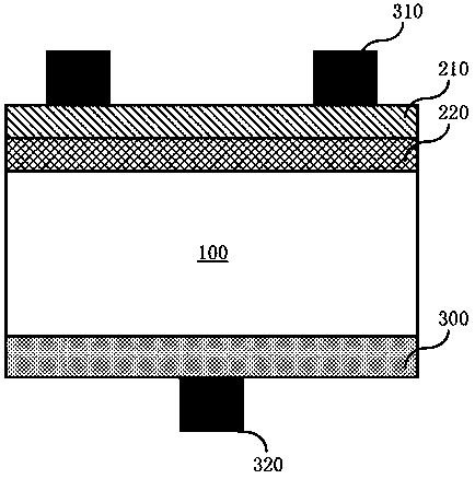
technical field [0001] The invention relates to the field of solar cells, in particular to a solar cell with an anti-PID passivation film. Background technique [0002] The long-term operation of photovoltaic modules under high-voltage conditions will cause leakage current between glass and packaging materials. When a large amount of charge accumulates on the surface of the battery sheet, the passivation effect of the battery surface will deteriorate, such as the fill factor (Fill Factor, FF), short-circuit current (Isc), and open-circuit voltage (Uoc) will decrease, which will lead to low module performance. on design standards. [0003] At present, the most widely used is to deposit Si on the front side (positive electrode side) of solar cells. x N y , increase Si x N y The refractive index of the film (as figure 1 shown); or deposit SiO on the front side of the cell 2 / Si x N y (Such as figure 2 shown) to achieve the effect of anti-PID (Potential Induced Degrad...

Claims


Application Information

Patent Timeline
IPC IPC(8): H01L31/0216
Inventor 单伟韩玮智牛新伟蒋前哨金建波陆川仇展炜
Owner ZHEJIANG ASTRONERGY
Learn More